
The Engineering Reality of DIY Soldering
When you are stranded in the field, working on a remote automotive repair, or simply operating on an ultra-strict budget, knowing how to make a homemade soldering iron transitions from a fun parlor trick to a critical survival skill. However, the internet is saturated with dangerous, poorly engineered DIY tutorials that result in scorched PCB pads, cold solder joints, and severe burn hazards. As electrical fabricators, we must approach DIY thermal tools with the same rigor we apply to commercial station selection.
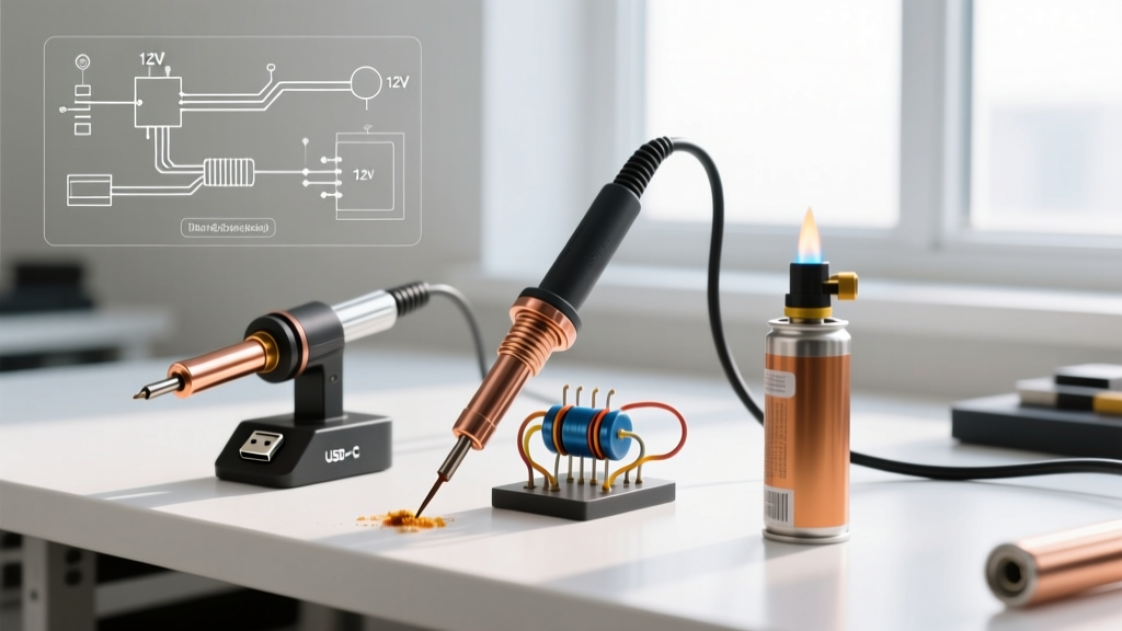
A reliable soldering iron requires three things: sufficient thermal mass, a controllable heat source, and an oxidation-resistant tip. In 2026, with the ubiquity of high-wattage USB-C Power Delivery (PD) infrastructure and advanced ceramic heater cartridges, building a DIY iron is more viable than ever. Below, we compare the three most effective methods for manufacturing a homemade soldering iron, evaluating them on thermal stability, build cost, and adherence to IPC-A-610 soldering acceptability standards.
Method 1: The USB-C PD Decoy Iron (Best Overall)
The modern standard for DIY electronics leverages USB-C Power Delivery. By using a PD decoy module, you can trick a standard 65W laptop charger or high-capacity power bank into outputting a fixed 20V DC, which is perfect for driving a ceramic heating core.
Components & Build Specifications
- Power Source: 65W USB-C PD wall adapter or power bank ($15-$25, assumed owned).
- Trigger Board: CH224K or ZYPDC01 USB-C PD decoy module, configured to 20V ($2.50).
- Heater: 24V 50W ceramic heater cartridge (6mm diameter x 30mm length) ($4.00).
- Tip: 6mm inner-diameter copper tube, capped and filed to a chisel point ($1.50).
- Enclosure: High-temperature silicone tubing and a 3D-printed PETG handle.
The Build Process
Wire the V+ and V- from the USB-C decoy module directly to the two leads of the ceramic heater cartridge. Solder the connections using high-temperature 63/37 eutectic solder and cover them with fiberglass heat-shrink tubing. Slide the copper tube over the ceramic heater. The ceramic core transfers heat to the copper sleeve via conduction. Wrap the rear of the assembly in silicone tubing to create a grip.
Pros and Cons
Pros: Reaches 320°C in under 45 seconds; highly portable; utilizes existing modern power infrastructure; relatively safe low-voltage DC operation.
Cons: Lacks active closed-loop temperature feedback (relies on the thermal equilibrium of the 50W heater); requires basic surface-mount soldering skills to assemble the decoy board if not pre-bought.
Method 2: The 12V Aluminum Resistor Iron (Best for Heavy Wire)
Before USB-C, the classic DIY heavy-duty iron relied on power resistors. This method is exceptionally rugged and ideal for soldering thick 10AWG or 8AWG wires, such as those found in automotive or solar battery banks, where high thermal mass is required to prevent the joint from acting as a heatsink.
Components & Build Specifications
- Power Source: 12V Sealed Lead-Acid (SLA) battery or vehicle battery.
- Heater: 50W 1-ohm aluminum-housed chassis mount resistor ($6.00).
- Tip: 8AWG solid copper wire, stripped and hammered flat at the tip.
- Hardware: Stainless steel hose clamps and mica insulator sheets.
The Build Process
Wrap the 8AWG copper wire tightly around the aluminum housing of the resistor. Secure it using two stainless steel hose clamps, ensuring bare metal-to-metal contact for maximum thermal transfer. Place a layer of mica between the resistor body and the hose clamps to prevent shorting if the clamps touch the internal element. Connect 14AWG silicone jumper wires to the resistor terminals, leading to an inline 10A automotive fuse and an alligator clip harness for the 12V battery.
Pros and Cons
Pros: Massive thermal mass; practically indestructible; extremely cheap to source parts; capable of soldering heavy-gauge battery cables.
Cons: Bulky and heavy; fixed temperature (dictated by ambient temp and battery voltage); takes 3-4 minutes to reach optimal 300°C operating temperature.
Method 3: The Butane & Copper Wire Iron (Best Off-Grid Survival)
When electricity is entirely unavailable, chemical combustion is your only option. The butane method uses a micro-torch to heat a thick copper wire. While crude, it is a vital skill for emergency field repairs in remote locations.
Components & Build Specifications
- Heat Source: Butane micro-torch (e.g., Dremel VersaTip or generic equivalent).
- Tip: 12AWG solid copper wire, 6 inches long.
- Handle: Wooden dowel with a drilled center hole and high-temp epoxy.
The Build Process
Drill a 2mm hole through the center of a 4-inch wooden dowel. Thread the 12AWG copper wire through the hole, leaving 2 inches protruding from the front. File the protruding copper into a sharp chisel or conical tip. Secure the wire at the back of the dowel using high-temperature JB Weld or a mechanical crimp. To use, apply the butane torch flame directly to the copper wire near the wooden handle base until the tip reaches a dull red glow, then allow it to cool slightly before tinning with rosin-core solder.
Pros and Cons
Pros: Zero electrical requirement; infinite portability; costs under $5 to build.
Cons: Severe oxidation issues (copper pits rapidly above 350°C); extreme risk of overheating and melting PCB pads; requires constant reheating during extended use.
Head-to-Head Comparison Matrix
| Feature | USB-C PD Decoy | 12V Resistor | Butane Torch |
|---|---|---|---|
| Estimated Build Cost | $8.00 - $12.00 | $10.00 - $15.00 | $3.00 - $5.00 |
| Heat-Up Time | 45 Seconds | 3.5 Minutes | 20 Seconds |
| Max Tip Temp | ~340°C | ~290°C | 400°C+ (Unregulated) |
| Temp Stability | Moderate (Passive) | Low (Fixed) | None (Manual) |
| Best Use Case | PCB & SMD Repair | Automotive/Solar Wire | Emergency Off-Grid |
Why Temperature Control Dictates Joint Reliability
Understanding why commercial stations cost upwards of $150 requires looking at industry standards. According to the IPC-A-610 standard for electronic assemblies, a proper Class 2 or Class 3 solder joint requires specific wetting angles and fillet shapes that are only achievable within a narrow thermal window. If your DIY iron runs too cold (below 250°C), the flux fails to activate, resulting in a cold, grainy joint with high electrical resistance. If it runs too hot (above 380°C), you risk delaminating the copper traces from the FR4 fiberglass substrate and burning out the flux before the solder flows.
The USB-C PD method wins our comparison because the 50W ceramic cartridge provides enough wattage to recover heat quickly when touching a ground plane, while naturally capping out around 340°C, which safely keeps you within the optimal window for 63/37 leaded solder (melting point 183°C) and SAC305 lead-free solder (melting point 217°C).
Health and Safety Protocols for DIY Irons
Building your own tool means you bypass the safety certifications (like UL or CE) found on commercial units. You must manually enforce safety protocols. The most significant hazard in soldering is not the heat, but the fumes. Rosin-based fluxes contain colophony, a known respiratory sensitizer that can cause occupational asthma. Furthermore, if you are using traditional 60/40 leaded solder, vaporized flux can carry microscopic lead particulates.
Always follow OSHA's guidelines on lead exposure and ensure you are working in a ventilated area. For DIY builds, we strongly recommend pairing your homemade iron with a desktop HEPA/Carbon fume extractor. Additionally, because DIY irons lack automatic sleep stands, you must fabricate a non-flammable holster (such as a bent steel wire rack or a ceramic crucible) to prevent the iron from rolling onto combustible surfaces when not in use.
Frequently Asked Questions
Can I use a standard 5V USB power bank for a DIY soldering iron?
No. Standard 5V USB outputs max out at 2.4A (12W), which is entirely insufficient to maintain the thermal mass required to melt solder and heat a copper tip. You must use a USB-C Power Delivery (PD) source capable of negotiating at least 20V at 2A or 3A (40W-60W) to achieve functional soldering temperatures.
How do I prevent the copper tip on my homemade iron from oxidizing and pitting?
Bare copper oxidizes rapidly when exposed to heat and atmospheric oxygen, creating a black copper oxide layer that solder will not adhere to. To mitigate this, you must 'tin' the tip immediately after heating. Coat the working end of the copper tip in a thick layer of rosin-core solder before turning the iron off. For a permanent fix, you can electroplate the copper tip with a thin layer of iron using a simple ferrous sulfate solution, mimicking the construction of commercial iron-plated copper tips.
Is it safe to use a 12V car battery resistor iron on sensitive microcontrollers?
It is highly discouraged. The 12V resistor iron has massive thermal inertia and lacks fine temperature control. While excellent for thick wires, applying it to a delicate 0.5mm pitch QFP microcontroller or a thin 2-layer PCB will almost certainly result in lifted pads, scorched silkscreen, and thermal damage to the silicon die. Reserve the resistor iron for heavy-gauge mechanical connections only.