
Diagnosing the Cold Tip: When Your Station Says It's Hot, But Solder Won't Melt
There are few things more frustrating in electronics assembly than watching your soldering station display 360°C while the solder wire simply bends against a seemingly cold tip. If you have ever found yourself asking, what is the soldering iron tip failing to transfer heat despite the station reading the correct temperature? The answer almost always lies in a breakdown of thermal transfer, a degraded heating element, or a compromised physical connection.
As of 2026, modern smart stations like the Pinecil V2, FNIRSI HS-01, and Hakko FX-951 utilize advanced PID controllers and rapid-response thermocouples. Yet, the fundamental physics of thermal transfer remain unchanged. This comprehensive troubleshooting and maintenance guide will help you isolate the exact failure point in your soldering setup, from the tip plating down to the handpiece connector.
The Diagnostic Matrix: Isolating the Failure Point
Before replacing expensive handpieces or scrapping perfectly good tips, use this diagnostic matrix to pinpoint the exact layer of failure. According to industry best practices outlined in the Adafruit Guide to Excellent Soldering, systematic isolation prevents unnecessary hardware replacement.
| Symptom | Station Display | Most Likely Culprit | Immediate Action |
|---|---|---|---|
| Solder balls up and rolls off tip | Normal (320°C+) | Severe tip oxidation (Black oxide layer) | Chemical tip tinner or brass wool cleaning |
| Solder melts sluggishly; joint is dull | Normal or slightly low | Micro-voids between tip and heater shaft | Reseat tip; check for bent shaft |
| Tip is completely cold to the touch | Reads ambient or throws Error (e.g., E01) | Broken ceramic heater or blown thermal fuse | Multimeter continuity test on handpiece |
| Station display flickers or resets | Erratic / Flashing | Cord flex fatigue or loose DIN connector pins | Wiggle test; inspect connector pinout |
Layer 1: Tip Oxidation and Thermal Blocking
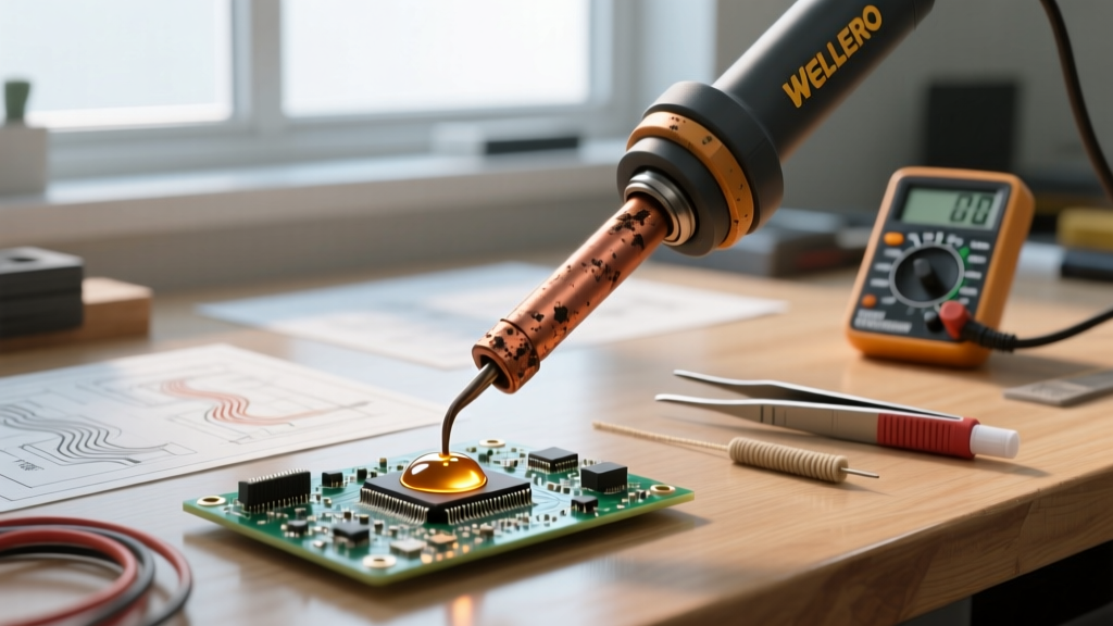
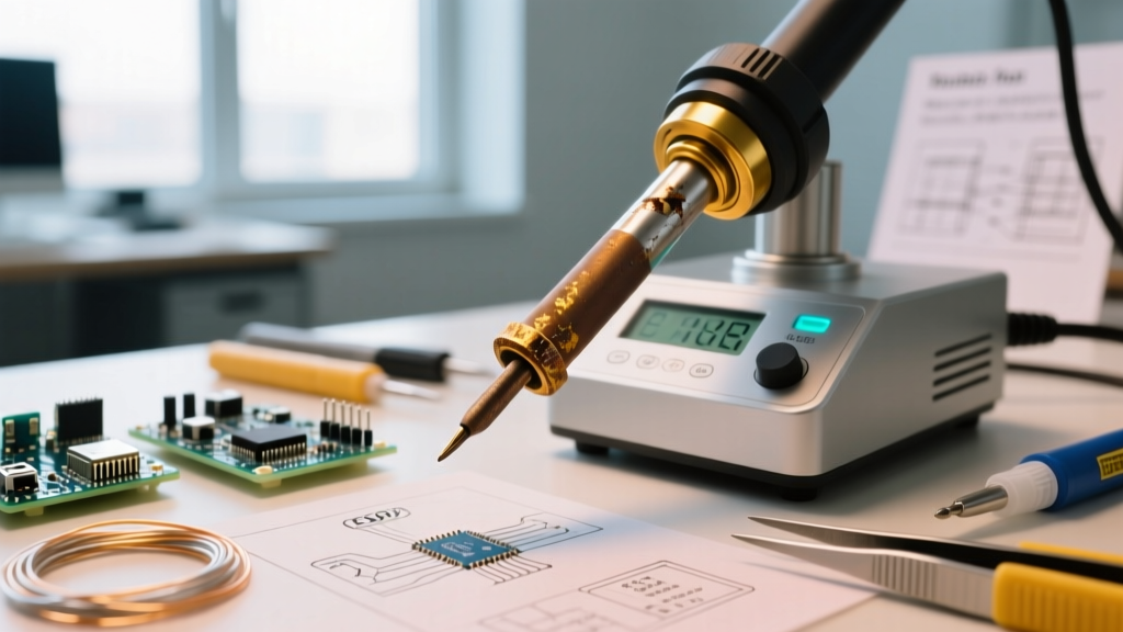
The most common reason a soldering iron appears to "not heat" is actually a failure of thermal coupling, not a failure of the heater itself. Soldering tips are typically constructed from a solid copper core, plated with iron (for durability), and finished with a micro-thin layer of chromium and tin. When the iron layer is exposed to high temperatures and atmospheric oxygen without a protective layer of molten solder or flux, it forms iron oxide.
The Physics of Oxide Insulation
Iron oxide is a thermal insulator. Even a microscopic layer of black oxidation will drop the surface temperature of the tip by 100°C to 150°C compared to the internal sensor reading. If you are running lead-free SAC305 solder (which requires 350°C–380°C), an oxidized tip reading 360°C on the dial might only be delivering 220°C to the solder joint—well below the 217°C melting point of the alloy, factoring in the thermal mass of the PCB pad.
Expert Warning: Never use a steel file, sandpaper, or an abrasive scouring pad to clean an oxidized tip. As noted in the SparkFun Soldering Tutorial, removing the iron plating exposes the raw copper core, which will rapidly dissolve into the molten solder, destroying the tip in minutes.
Restoring a Severely Oxidized Tip
- Lower the Temperature: Drop your station to 250°C. High heat accelerates oxidation and burns off flux before it can clean the surface.
- Apply Flux Core: Melt a generous amount of high-flux (RMA or RA) rosin-core solder directly onto the blackened area. The activated rosin will chemically reduce the iron oxide.
- Brass Wool Agitation: Gently wipe the tip in a damp brass wire sponge. The brass is softer than the iron plating but harder than the oxide layer.
- Retin Immediately: Once the shiny iron plating is exposed, immediately coat it with a thick layer of fresh Sn63/Pb37 or SAC305 solder to prevent flash-oxidation.
Layer 2: Heating Element and Sensor Failures
If the tip is clean, shiny, and properly seated, but remains completely cold, the fault lies within the handpiece. Modern stations use either composite tips (where the heater and sensor are built into the tip, like the Hakko T12 or Pinecil V2) or separate ceramic heaters (like the Hakko FX-888D or Weller WE1010).
Multimeter Testing Procedures
To test the heating element, unplug the station from the mains. Set your digital multimeter to the lowest Ohms (Ω) setting. Access the pins on the handpiece connector (or the base of the tip for composite models).
- Hakko FX-888D (T18 Series / 907 Handpiece): Measure between pins 1 and 2 (heater). You should read between 2.5Ω and 3.5Ω. Measure between pins 3 and 4 (sensor). You should read approximately 45Ω to 55Ω. An open loop (OL) on either indicates a severed internal wire or blown element.
- Weller WE1010 (ETA Tip): The heating element is integrated into the tip. Measure across the two main power contacts on the tip base. Expected resistance is 3.0Ω to 4.5Ω.
- Pinecil V2 (Composite Tip): Measure across the two outermost power pads on the base of the tip. Resistance is extremely low, typically 1.2Ω to 1.8Ω. The inner pins handle the thermocouple micro-voltages.
The "Percussive Maintenance" Failure Mode
A frequent cause of sudden heater failure in ceramic-element stations (like the classic Hakko 936 or FX-888D) is tapping the handpiece against the workbench or solder sponge to knock off excess solder. The ceramic heater rod inside the handpiece is highly brittle. A sharp mechanical shock will cause a micro-fracture in the ceramic, instantly breaking the internal tungsten heating trace. Always use a brass sponge or a gentle wiping motion; never strike the iron.
Layer 3: Cord Fatigue and Connector Pinout Issues
If your multimeter shows correct resistance at the handpiece connector, but the station still throws an error or fails to heat, the issue is likely in the cord or the station-side receptacle. Silicone-jacketed cords are highly heat resistant but suffer from copper strand fatigue near the strain relief boot after years of rotational twisting.
Performing the Wiggle Test
Power on the station and set it to 300°C. While monitoring the temperature display or the heating indicator LED, gently bend and twist the cord at three critical stress points:
- Directly behind the handpiece strain relief.
- At the midpoint of the cord (if it has been tightly wrapped).
- At the station-side DIN or aviation plug.
If the station display flickers, resets, or the heating light drops out during the test, you have an internal copper break. For high-end stations like the Pace ADS200 or JBC CD-2BQE, replacing the cord assembly is a standard $30–$50 maintenance procedure. For budget stations, splicing a new silicone wire harness is a common DIY repair, provided you maintain the correct gauge (typically 24 AWG for heater lines, 28 AWG for sensor lines) to avoid introducing voltage drop that confuses the PID controller.
Proactive Maintenance Schedule for 2026
Preventing thermal transfer issues is vastly superior to troubleshooting them. Implement this maintenance schedule in your lab or workshop to maximize tip life and ensure consistent thermal recovery.
| Frequency | Maintenance Task | Technical Rationale |
|---|---|---|
| Daily (End of Shift) | Retin the tip with a thick blob of rosin-core solder before powering off. | Creates an oxygen barrier, preventing iron plating oxidation during the cool-down phase. |
| Weekly | Remove the tip from the heater shaft and apply a microscopic layer of high-temp anti-seize or pure rosin. | Prevents galvanic corrosion and seizing between the copper/iron tip and the ceramic/alumina shaft. |
| Monthly | Inspect station-side and handpiece-side connector pins for oxidation or splaying. | Ensures low-resistance electrical contact for accurate sensor readings and full power delivery. |
| Annually | Calibrate station temperature using a digital tip thermometer (e.g., Hakko FG-100B). | Compensates for thermocouple drift and ensures compliance with IPC J-STD-001 thermal profiles. |
Final Thoughts on Soldering Iron Diagnostics
Understanding what is the soldering iron failing to do—and why—requires looking past the digital display and evaluating the physical chain of thermal and electrical conductivity. Whether you are dealing with a microscopic layer of iron oxide blocking heat transfer, a fractured ceramic core from bench-tapping, or a fatigued wire in the handpiece cord, systematic troubleshooting will save you time and money. Keep your tips tinned, your brass sponge clean, and your multimeter handy, and your soldering station will deliver flawless thermal recovery for years to come.