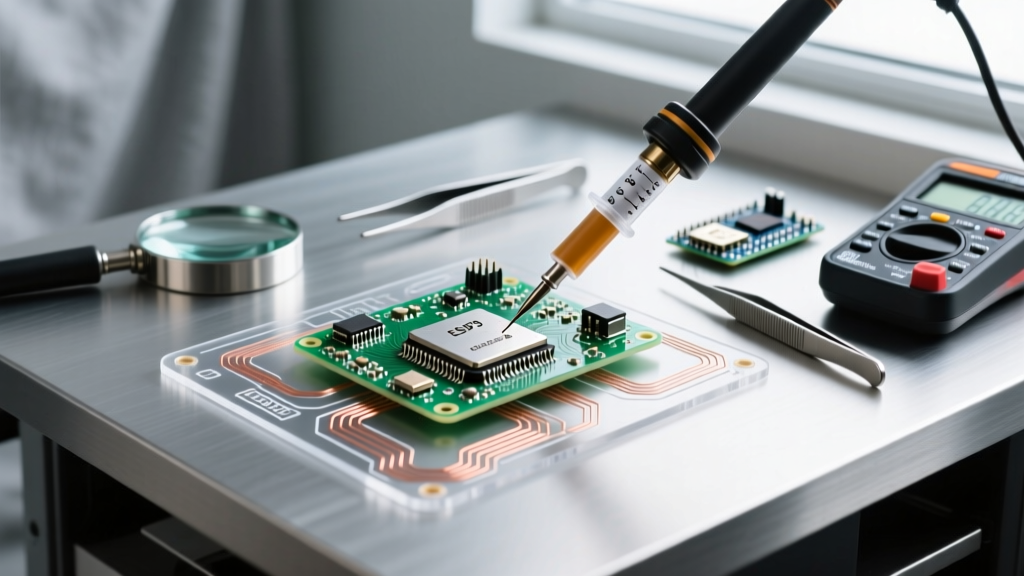

Beyond the Basics: What Is Soldering Paste Used For?
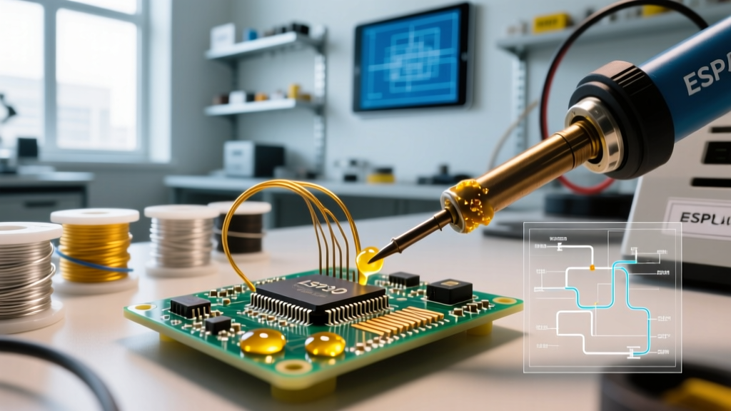
When transitioning from basic through-hole soldering to modern surface mount technology (SMT), hobbyists and professionals alike inevitably ask: what is soldering paste used for? Unlike traditional solder wire, which relies on a solid flux core and manual heat application, solder paste is a sophisticated, homogeneous mixture of microscopic solder alloy spheres suspended in a tacky flux vehicle. It is the foundational material for automated reflow soldering, precision stencil printing, and complex component rework.
While solder wire is ideal for wiring and large through-hole components, solder paste is engineered for scenarios where manual iron placement is physically impossible or economically unviable. This guide breaks down the exact applications, metallurgical classifications, and selection frameworks you need to choose the right paste for your 2026 production or prototyping runs.
Core Applications: Where Solder Paste Outperforms Wire
Solder paste is not merely an alternative to wire; it is a necessity for specific manufacturing and repair workflows. Here is where paste is strictly required:
- Surface Mount Technology (SMT) Assembly: Applied via laser-cut stencils, paste provides the exact volume of solder and flux needed to simultaneously attach hundreds of surface-mount components during reflow.
- BGA and QFN Rework: Ball Grid Arrays (BGAs) and Quad Flat No-leads (QFNs) have hidden thermal pads or underside solder balls. Paste is essential for reballing BGAs or securing the ground pads of QFN chips using hot air or infrared reflow stations.
- Drag Soldering Fine-Pitch ICs: For 0.5mm pitch TQFP chips, applying a thin layer of paste and dragging a wide iron tip across the pins yields cleaner joints than attempting wire-feed bridge removal.
- Pre-tinning Complex Ground Planes: High-thermal-mass PCB ground planes often reject standard wire solder. Paste lowers the surface tension and pre-fluxes the area, allowing uniform wetting when heat is applied.
The Anatomy of Solder Paste
To understand what soldering paste is used for, you must understand its composition. According to the IPC J-STD-005 standard, paste is typically 85% to 92% solder powder by weight, with the remainder being the flux vehicle. The flux vehicle dictates the paste's tackiness (how well it holds components in place before reflow), its shelf life, and its post-reflow residue characteristics.
Solder Paste Types & Alloy Selection Matrix
Selecting the correct alloy depends on your thermal budget, regulatory requirements (RoHS), and the components on your board. Below is a comparison of the most prevalent alloys used in modern electronics assembly.
| Alloy Designation | Composition | Melting Point | Primary Use Case | 2026 Est. Cost (500g Jar) |
|---|---|---|---|---|
| SAC305 | 96.5Sn / 3.0Ag / 0.5Cu | 217°C - 220°C | Standard RoHS-compliant commercial SMT assembly. | $130 - $165 |
| Sn63Pb37 | 63Sn / 37Pb | 183°C (Eutectic) | Legacy repair, aerospace, hobbyist prototyping. | $95 - $120 |
| Sn42Bi58 | 42Sn / 58Bi | 138°C | Heat-sensitive components, flexible PCBs, step-soldering. | $150 - $180 |
| SAC405 | 95.5Sn / 4.0Ag / 0.5Cu | 217°C - 220°C | High-reliability automotive and harsh-environment boards. | $145 - $175 |
Powder Size: Matching Paste to Component Pitch
A critical mistake beginners make is ignoring the IPC powder size classification. The physical size of the solder spheres determines whether the paste will clog your stencil or bridge fine-pitch pads.
Expert Insight: Never use Type 3 paste for 0402 components. The large solder spheres will cause inconsistent deposition, leading to tombstoning or insufficient solder volume. Always scale down your powder size as component pitch decreases.
- Type 3 (25–45 µm): The workhorse for standard SMT. Ideal for 0805, 1206, and SOIC packages. Best used with 5-mil to 6-mil thick stencils.
- Type 4 (20–38 µm): Required for 0402, 0603, and fine-pitch QFPs (0.5mm). This is the default choice for most modern 2026 prototyping labs.
- Type 5 (15–25 µm): Reserved for ultra-fine 0201 components, 0.4mm pitch CSPs, and micro-BGA reballing. Requires highly precise 3-mil stencils and electro-polished aperture walls.
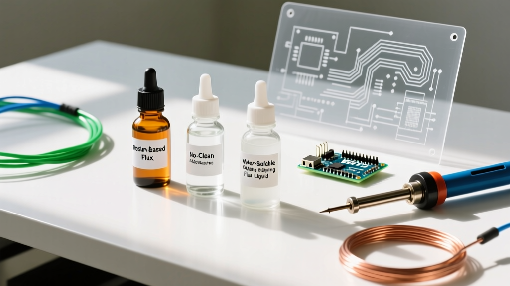
Flux Chemistries: No-Clean vs. Water-Soluble
The flux vehicle inside the paste is just as important as the metal. Major manufacturers like Indium Corporation formulate distinct flux profiles to match post-assembly cleaning capabilities.
1. No-Clean (ROL0 / ROL1)
No-clean pastes leave a transparent, hard, and non-corrosive residue after reflow. They are classified as ROL0 (Rosin, Low activity, no halides). This is the industry standard for consumer electronics where aesthetic cleaning is skipped to save manufacturing costs. However, the residue can interfere with bed-of-nails ICT (In-Circuit Testing) if not formulated for probe-ability.
2. Water-Soluble (OA)
Water-soluble pastes contain highly active organic acids (OA) designed to cut through heavy oxidation on aged pads or nickel-gold (ENIG) finishes. Warning: The residue is highly corrosive and conductive. If you use water-soluble paste, the PCB must be cleaned with heated deionized water and saponifiers within 4 hours of reflow to prevent dendritic growth and catastrophic short circuits.
Step-by-Step: Manual Syringe Application for Rework
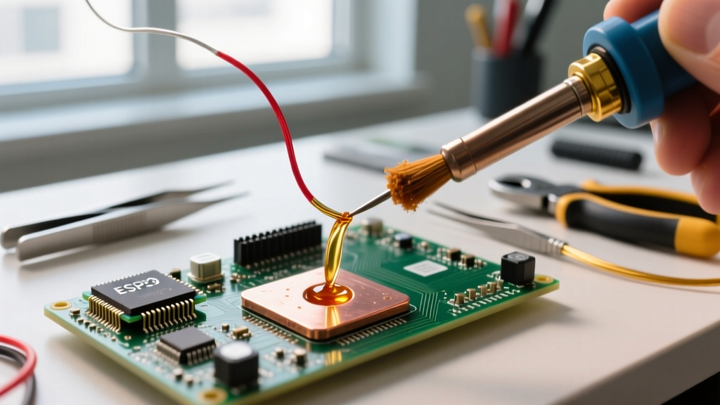
While jars are used for stencil printing, 10cc or 35cc syringes are the standard for manual rework and hot-air soldering. Here is the professional workflow for applying paste via syringe:
- Acclimatize the Paste: Paste is stored at 0°C–10°C. Remove the syringe from refrigeration and let it sit at room temperature for at least 2 hours before opening. Opening a cold syringe causes ambient moisture to condense into the paste, resulting in violent spattering (solder balling) during reflow.
- Dispense with Precision: Using a pneumatic dispenser or a steady hand, apply a small dot to the center of the pad. For a standard 0805 pad, the deposited volume should not exceed 50% of the pad's surface area.
- Component Placement: Use ESD-safe tweezers to place the component. The tackiness of the flux will hold it in place. Do not press down so hard that the paste squirts out from under the component.
- Hot Air Reflow: Set your hot air station to 300°C–350°C (depending on airflow and board mass). Pre-heat the board from a distance to allow the flux to activate and outgas (usually 150°C for 60 seconds), then focus the air directly on the joints until the paste transitions from a dull grey to a shiny, liquid metallic pool.
Common Failure Modes & Troubleshooting
Understanding what soldering paste is used for also means knowing how it fails. If your reflow results are poor, check these common edge cases:
- Tombstoning: A passive component stands up on one end. This is caused by uneven heating (one pad reaches reflow temperature before the other) or excessive paste volume creating unequal surface tension forces.
- Solder Balling / Spattering: Tiny spheres of solder scatter across the board. This is almost always caused by moisture trapped in the paste (failure to acclimatize) or a reflow ramp-up rate that is too aggressive, boiling the flux solvents instantly.
- Voiding: X-ray inspection reveals empty pockets inside large thermal pads (like those on QFNs). To mitigate this, use a paste with a low-voiding flux formulation (often classified as Type 4 or specialized void-reduction alloys) and ensure your PCB layout includes via-in-pad tenting or outgassing channels.
Storage and Shelf Life Realities
Solder paste is a perishable chemical product. A sealed jar of SAC305 Type 4 no-clean paste typically has a shelf life of 6 months when stored continuously between 0°C and 10°C. Once opened, the clock accelerates. Exposure to ambient humidity and the mechanical shearing action of a squeegee degrade the flux's rheology (its ability to flow and release from the stencil). For high-reliability aerospace or medical builds, discard paste that has been left on the stencil for more than 12 hours, or refer to the manufacturer's specific technical data sheets for exact pot-life metrics.
Ultimately, mastering solder paste unlocks the ability to work with the dense, high-pin-count microprocessors and RF modules that define modern electronics. By matching the correct alloy, powder size, and flux chemistry to your specific application, you ensure robust, defect-free solder joints every time.