
The Anatomy of a Perfect Connector Joint
When beginners ask how to solder wires to connectors, they often focus entirely on the soldering iron's wattage or temperature. However, the true secret to a reliable, low-resistance joint lies in your consumables. Whether you are assembling XT60 battery plugs, terminating JST-XH balance leads, or wiring Molex PicoBlade harnesses, the interaction between your solder alloy, flux chemistry, and the connector's metallization dictates the success of the joint. A poorly chosen flux can lead to latent corrosion inside a plastic housing, while the wrong solder alloy can cause a 'plastic phase' fracture if the wire moves during cooling. This guide strips away the guesswork, focusing on the exact consumables and techniques required to master connector soldering.
Choosing the Right Consumables for Connectors
Before your iron even touches the copper, you must select the correct chemical and metallic partners for your specific connector type. Connector pins are typically brass or phosphor bronze, plated with tin, nickel, or gold. These platings oxidize, and breaking through that oxidation requires the right flux.
Solder Alloys: Why Eutectic is King for Beginners
For through-hole connector pins and solder cups, we strongly recommend a 63/37 (Tin/Lead) eutectic solder, such as Kester 245. Unlike 60/40 solder, which has a 'plastic phase' (a temperature range where the solder is partially solid and partially liquid), 63/37 transitions instantly from liquid to solid at exactly 183°C (361°F). When soldering wires to connectors, the wire is highly susceptible to micro-movements from your hands or the tension of the silicone jacket. If the wire moves while a 60/40 joint is in its plastic phase, the internal crystalline structure fractures, resulting in a grainy, high-resistance cold joint. Eutectic solder eliminates this risk entirely. For wire gauges between 18 AWG and 24 AWG, select a solder wire diameter of 0.8mm (0.031 inches) with a 2% to 3% rosin core.
Flux Selection: The Unsung Hero of Wetting
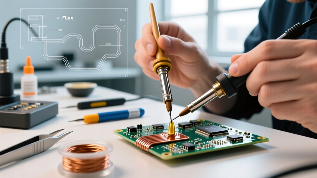
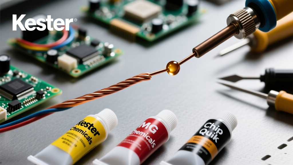
While rosin-core solder contains some flux, it is rarely sufficient for the thermal mass of a connector pin. You must use an external flux. According to the NASA-HDBK-8739.3 Workmanship Manual, proper wetting relies on the flux lowering the surface tension of the molten solder while simultaneously stripping copper oxide. For connectors, use a Rosin-Based (R) or Mildly Activated Rosin (RMA) liquid flux, like Kester 951 or MG Chemicals 8341. Never use water-soluble (organic acid) fluxes on connectors. Water-soluble fluxes are highly corrosive and conductive; if they wick into the plastic housing of a JST or Molex connector, they will cause dendritic growth and short circuits over time. No-clean fluxes are an acceptable alternative, provided you do not bridge adjacent pins.
Step-by-Step: How to Solder Wires to Connectors
With your 63/37 eutectic solder and RMA flux prepared, you can begin the physical process. The golden rule of connector soldering is separate preparation, unified mating.
Phase 1: Wire and Connector Preparation
- Slide on Heat Shrink: Always slide your heat shrink tubing onto the wire before doing anything else. For connectors subject to vibration (like RC models or automotive harnesses), use dual-wall adhesive heat shrink. The inner meltable adhesive provides crucial strain relief at the solder joint.
- Strip the Wire: Strip exactly 3mm to 5mm of insulation. Exposed wire that extends past the connector cup will cause stray strands to short against adjacent pins or the connector shell.
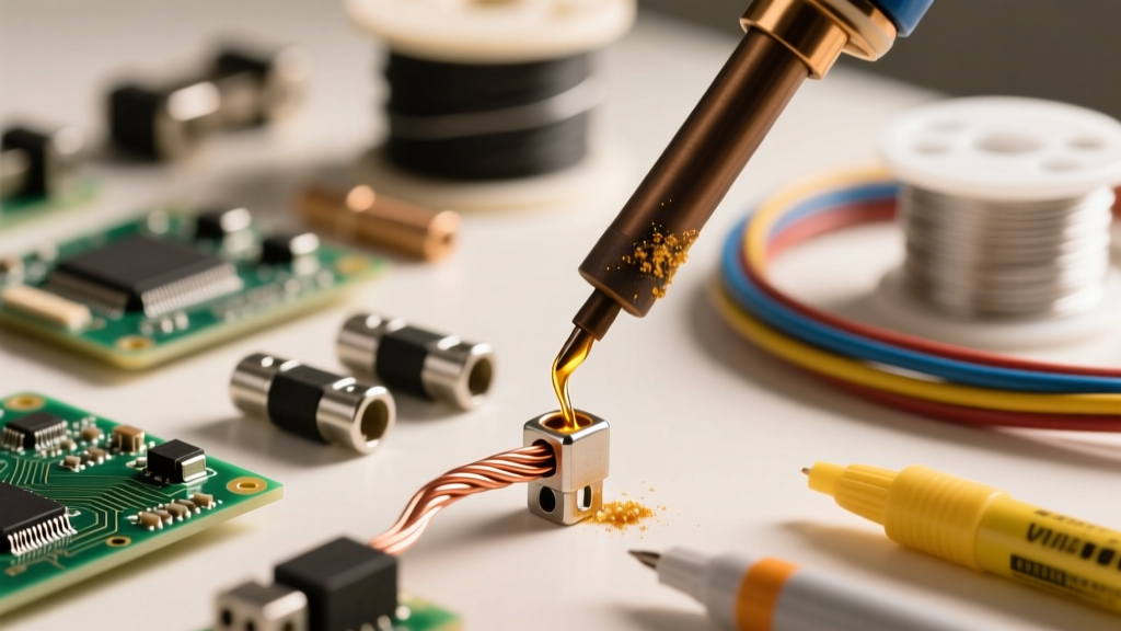
- Pre-Tin the Wire: Apply a tiny drop of liquid flux to the stripped copper. Touch your 360°C chisel-tip iron to the wire and feed the solder until the strands wick together into a solid, shiny cylinder. Do not create a bulbous blob; the tinned wire should retain the profile of the original strands.
- Pre-Tin the Connector Cup: Hold the connector in a 'helping hands' vise. Apply a micro-drop of flux to the solder cup or pin. Touch the iron to the cup and feed a small amount of solder to coat the inside. Remove the iron immediately.
Phase 2: Heat Management and Mating
Connector housings are typically made of PBT (Polybutylene Terephthalate) or Nylon 66, which have melting points ranging from 220°C to 260°C. Your iron is set to 360°C. This means your dwell time must remain under 3 seconds per joint to prevent the plastic from deforming and losing its pin-retention grip.
- Insert the pre-tinned wire into the pre-tinned connector cup.
- Apply the flat face of your chisel tip to the side of the connector cup, bridging the thermal gap between the cup and the wire.
- Hold for 1.5 to 2 seconds. The existing solder on both the wire and the cup will melt simultaneously, aided by the residual flux.
- Remove the iron and hold the wire perfectly still for 2 seconds while the 63/37 eutectic solder flashes from liquid to solid.
Phase 3: Inspection and Strain Relief
A proper solder cup joint should show a smooth, concave fillet where the wire meets the cup. The solder should not climb up the wire insulation. Once the joint is cool to the touch, slide the dual-wall heat shrink up to the connector housing and apply heat. The adhesive will melt and squeeze out the ends, locking the wire to the connector and preventing mechanical fatigue from breaking the solder joint.
Troubleshooting Common Connector Soldering Failures
Even with the best consumables, beginners encounter specific failure modes. The IPC J-STD-001 standard provides strict criteria for these defects. Use this table to diagnose and fix your joints.
| Failure Mode | Visual Cue | Consumable or Technique Fix |
|---|---|---|
| Melted Housing | Plastic deformed, pin pushed back | Switch to 63/37 eutectic solder for faster wetting; ensure iron tip is clean and tinned for maximum thermal transfer; reduce dwell time. |
| Cold Joint | Dull, grainy, or lumpy surface | Wire moved during the plastic phase. Use eutectic solder; apply more RMA flux to lower surface tension; increase iron temp by 10°C. |
| Solder Wicking | Solder climbs under the wire insulation | Strip wire properly; avoid over-tinning the wire before insertion; use a smaller solder wire diameter (e.g., 0.5mm). |
| Flux Entrapment | Bubbles or voids inside the solder fillet | Flux boiled but couldn't escape. Apply flux only to the wire, not the bottom of the cup; ensure adequate heating time for volatiles to vent. |
| Non-Wetting | Solder balls up and refuses to stick | Heavy oxidation on gold/nickel plated pins. Use a mildly activated (RMA) flux; lightly scuff the pin with a fiberglass scratch pen before tinning. |
Essential Safety and Cleanup Protocols
Soldering connectors often requires holding the plastic housing near the heat source. Always use a silicone mat or a ceramic tile as your work surface. When using RMA or No-Clean fluxes, the residue is generally benign, but it can attract dust and moisture over time in high-humidity environments. As detailed in the Kester Flux Chemistry Guide, if you are operating in harsh environments, clean the connector housing with high-purity (99%+) isopropyl alcohol and a stiff-bristled ESD-safe brush before applying any conformal coating or potting compound.
Pro Tip: Never use a conical (pointed) tip for soldering wires to connectors. Conical tips have terrible thermal mass transfer. Always use a bevel or chisel tip that matches the width of the connector's solder cup to ensure rapid, even heating.
Mastering how to solder wires to connectors is less about hand-eye coordination and more about respecting the chemistry of your flux and the metallurgy of your solder. By standardizing your bench with 63/37 eutectic solder, RMA liquid flux, and dual-wall heat shrink, you will eliminate 90% of the mechanical and electrical failures that plague beginner harness builds.