
Mastering Wire Holder Soldering: The Ultimate FAQ & Troubleshooting Guide
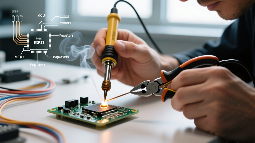
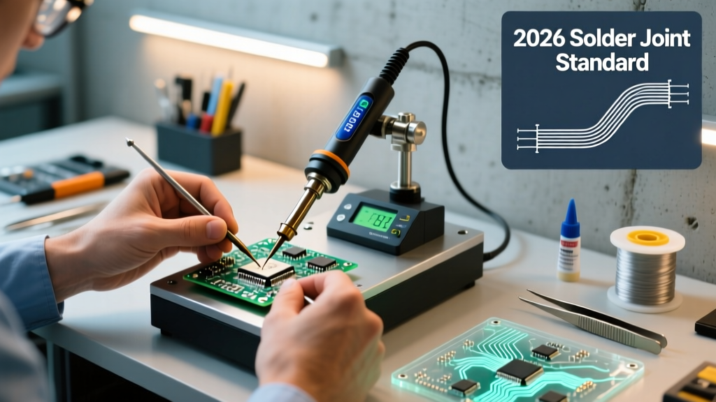
Soldering wires to terminals, PCBs, or other wires requires absolute mechanical stability. A micro-movement during the liquidus phase of the solder alloy creates a 'disturbed joint,' a critical defect outlined in the IPC-A-610 Acceptability of Electronic Assemblies standard. This is where wire holder soldering becomes essential. However, introducing a clamping mechanism into your workflow brings unique thermal and mechanical challenges. In this comprehensive FAQ and troubleshooting guide, we address the most common failure modes associated with wire holding jigs, helping hands, and magnetic clamps, providing actionable solutions for both hobbyists and professional harness builders.
Frequently Asked Questions (FAQ)
1. Why do my solder joints look dull and grainy when using a heavy metal wire holder?
This is the most common issue in wire holder soldering, caused by 'heat sinking.' When you clamp a thick copper wire (e.g., 14 AWG) with a standard steel alligator clip, the mass of the metal clip acts as a massive thermal sink. It pulls heat away from the joint faster than your soldering iron can replenish it. As a result, the solder cools prematurely while still in a semi-solid state, resulting in a dull, grainy, and structurally weak cold joint. To fix this, you must either increase your iron's temperature by 20°C to 30°C, switch to a higher thermal mass tip (like a chisel instead of a conical), or use wire holders with silicone or ceramic-isolated jaws.
2. What is the ideal clamping distance from the solder joint?
The optimal distance depends entirely on the American Wire Gauge (AWG) and the insulation material. For thin 22-26 AWG wires, keep the clamp approximately 15mm (0.6 inches) away from the stripped end. For thicker 10-14 AWG wires, increase this distance to at least 30mm (1.2 inches). Clamping too close to the joint on thick wires causes two issues: the clamp absorbs the heat needed for the joint, and the thermal conductivity of the copper will transfer heat directly into the clamp, potentially scorching or melting PVC and Teflon insulation jackets.
3. Are silicone-tipped wire holders better than bare alligator clips?
For modern electronics and delicate wire harnesses, yes. Bare steel alligator clips (often found on cheap $15 helping hands) can mar copper strands, cause short circuits if they touch adjacent terminals, and aggressively sink heat. Silicone-tipped flexible arm holders, such as the QuadHands Workbench (typically priced around $45), provide electrical isolation, protect delicate wire strands from crushing, and drastically reduce thermal transfer. However, for heavy-duty automotive 8 AWG battery cables, a heavy steel Vise-Grip style holder is preferred because the thermal mass is less of an issue when using high-wattage irons (100W+).
Troubleshooting Matrix: Wire Holder Soldering Defects
Use the following diagnostic table to identify and resolve specific defects caused by improper wire holding techniques.
| Symptom | Root Cause | Technical Fix |
|---|---|---|
| Solder balls up and refuses to wet the wire strands. | Flux burn-off due to prolonged heating caused by clip heat-sinking. | Upgrade to silicone-jaw clips or increase iron temp by 25°C. Apply secondary liquid flux immediately before heating. |
| Wire insulation melts, shrinks, and exposes bare copper. | Clamp placed too close, conducting heat into the PVC/Teflon jacket. | Move the clamp back at least 20mm. Use a ceramic-tipped holder or apply a thermal paste barrier. |
| Joint fractures under mild physical tension. | Disturbed joint from a loose spring-tension clip slipping during cooling. | Switch to a screw-down vise or a magnetic wire jig with high-friction silicone pads. |
| Solder wicks up the wire too far, stiffening the flexible joint. | Capillary action accelerated by holding the wire vertically downwards. | Always clamp wires horizontally or slightly upwards to prevent gravity-assisted solder wicking. |
Buyer's Comparison: Types of Wire Holding Jigs
Choosing the right hardware for wire holder soldering depends on your production volume and wire gauge. Here is how the top three categories compare in a modern 2026 workbench setup:
- Standard Helping Hands (e.g., Hakko CHP HP-40, ~$22): Features rigid metal arms and bare alligator clips. Best for occasional hobbyist use and 20+ AWG signal wires. Poor thermal isolation.
- Silicone-Tipped Flexible Arms (e.g., QuadHands Workbench, ~$45): Features bendable aluminum arms with high-friction silicone pads. Excellent thermal isolation and wire protection. Ideal for PCB-to-wire connections and 18-26 AWG harnesses.
- Magnetic Wire Jigs (e.g., MakerBeam Magnetic Bases, ~$35 for a set): Heavy neodymium magnetic bases with silicone V-grooves. Best for repetitive wire harness building on a steel workbench. Allows rapid repositioning without loosening screws.
- Locking Pliers / Vise-Grips (e.g., Irwin Vise-Grip 5R, ~$18): High clamping force, massive thermal sink. Strictly for heavy-gauge automotive or RC battery wires (8-12 AWG) paired with 100W+ soldering stations.
Advanced Thermal Management for Clamped Wires
According to Hakko USA's soldering best practices, matching your tip geometry to the thermal load of the joint is critical. When a wire holder is introduced, you are effectively adding a third thermal mass to the equation (Iron Tip + Wire + Clamp).
If you are clamping a 12 AWG wire using a standard steel vise, a standard conical tip will fail to transfer adequate heat. Instead, configure a station like the Weller WE1010 with an RT4 (chisel) tip and set the temperature to 380°C (716°F). The chisel tip maximizes surface area contact, pushing through the thermal deficit created by the steel clamp. Conversely, if you are using a thermally isolated silicone magnetic jig for 24 AWG wire, drop the temperature to 320°C (608°F) with an RT1 (micro conical) tip to prevent blowing out the delicate copper strands.
'A disturbed solder joint is characterized by a grainy, dull appearance and is caused by movement of the components during the solidification phase. Proper mechanical fixation, such as a calibrated wire holder, is mandatory for IPC-compliant assemblies.' — SparkFun Soldering Tutorial & IPC Guidelines
Step-by-Step: Calibrating Your Setup for High-AWG Wires
When wire holder soldering for heavy-duty applications (10 to 14 AWG), follow this exact sequence to ensure a flawless, high-tensile joint:
- Pre-Tin the Wire: Strip the wire and apply a light coat of solder to the bare strands before placing it in the holder. This prevents the holder's jaws from crushing loose strands and improves thermal conductivity.
- Position and Clamp: Secure the wire in a silicone-lined magnetic jig, ensuring at least 30mm of clearance between the jaw and the stripped end.
- Apply Secondary Flux: Brush a high-quality no-clean or rosin flux (e.g., Amtech NC-559) onto the pre-tinned wire and the terminal.
- Engage the Iron: Press a pre-heated chisel tip (minimum 360°C) against both the terminal and the wire simultaneously for 2-3 seconds.
- Feed Solder: Apply 63/37 eutectic solder to the opposite side of the joint. Capillary action will pull the solder through the strands.
- Cool in Place: Remove the iron and hold the wire holder completely still for 4-5 seconds until the solder transitions from shiny liquid to a solid, bright satin finish.
By understanding the thermal dynamics between your clamping tools and your soldering station, you can eliminate cold joints, protect expensive wire insulation, and achieve professional-grade mechanical and electrical connections every time.