
The Electromechanical Challenge of Soldering Switches
Soldering switches presents a unique thermal and mechanical challenge for DIY electronics builders and professional technicians alike. Unlike standard printed circuit board (PCB) components, panel-mount switches—such as toggles, pushbuttons, and rockers—feature heavy copper or brass solder lugs that act as massive heat sinks. If you apply heat incorrectly, you risk thermal runaway, which can melt the phenolic or nylon switch housing, warp the internal contact leaf, or vaporize the factory-applied contact grease.
This comprehensive guide covers the exact techniques, tooling, and buyer specifications you need to successfully integrate electromechanical switches into your 2026 projects, ensuring high-reliability connections that meet modern industry standards.
Understanding Switch Types and Terminal Styles
Before picking up your iron, it is critical to understand the physical construction of the switch you are wiring. The terminal style dictates your soldering approach.
- Solder Lug Terminals: Found on heavy-duty toggle and rocker switches (e.g., NKK M-Series or Carling V-Series). These feature a stamped metal eyelet. They require high thermal transfer and mechanical wire wrapping before soldering.
- PCB Mount (Through-Hole): Common in tact switches and DIP switches. These have thin metal pins designed to be inserted into plated through-holes. They are highly sensitive to excessive heat, which can delaminate the internal switch contacts.
- Quick-Connect (Spade) Terminals: While designed for crimping, many DIYers solder wires directly to 0.187" or 0.250" spade terminals. This requires a high-wattage iron to overcome the massive thermal mass of the spade.
Buyer's Matrix: Selecting the Right Switch Specifications
When purchasing switches for a custom control panel, audio amplifier, or automotive project, do not just look at the physical footprint. You must match the electrical and thermal ratings to your application. Below is a comparison matrix of common switch categories available on the market today.
| Switch Category | Typical Current Rating | Terminal Style | Housing Material | Best Application |
|---|---|---|---|---|
| Miniature Toggle (e.g., NKK M-Series) | 3A - 6A @ 125VAC | Solder Lug / PCB | Thermoset Phenolic | Audio routing, low-power logic |
| Heavy-Duty Rocker (e.g., Carling V-Series) | 15A - 20A @ 12VDC | Solder Lug / Spade | Nylon / Polycarbonate | Automotive, marine panels |
| Momentary Pushbutton (e.g., E-Switch TL Series) | 0.4VA - 1A @ 20V | Solder Lug / PCB | PBT / Epoxy | Instrumentation, foot pedals |
| Snap-Action Microswitch (e.g., Omron V-Series) | 10A - 15A @ 250VAC | Solder Tab / Screw | Phenolic Resin | Limit switches, interlocks |
Note: Always check the manufacturer's datasheet for specific DC ratings. A switch rated for 15A at 120VAC may only handle 2A at 12VDC due to the lack of an alternating current zero-crossing to extinguish the electrical arc.
Essential Tooling for High Thermal Mass Terminals
The most common mistake when soldering switches is using an underpowered iron or the wrong tip geometry. According to best practices outlined in the SparkFun Through-Hole Soldering Tutorial, matching your tip to the thermal mass of the joint is critical.
- Soldering Station Wattage: Use a temperature-controlled station capable of delivering at least 60W to 80W of continuous power (e.g., Weller WE1010 or Hakko FX-951). Low-wattage irons will suffer from thermal droop when touching a heavy brass lug.
- Tip Geometry: Never use a conical (pointed) tip for solder lugs. Conical tips have minimal surface area contact, forcing you to hold the iron on the joint for 10+ seconds, which guarantees a melted switch housing. Use a chisel tip (like the Hakko T18-D24 or Weller RTD) or a bevel tip to maximize surface area contact and transfer heat in under 3 seconds.
- Solder Alloy: For DIY and repair, 63/37 (Tin/Lead) eutectic solder with a rosin core (0.8mm / 0.031" diameter) is ideal due to its lower melting point (183°C). If you must use lead-free SAC305 for RoHS compliance, expect to increase your iron temperature to 350°C - 380°C and use an active flux gel.
- Heat Sinks: Keep a pair of copper alligator clips or specialized hemostats on hand. Clipping them onto the solder lug between the joint and the switch body absorbs excess heat, protecting the internal mechanics.
Step-by-Step: How to Solder Lug and PCB Switches
Follow this procedure to ensure a joint that meets the mechanical and electrical requirements of the IPC J-STD-001 Standard for soldered electrical assemblies.
Step 1: Mechanical Preparation (The Wrap)
Solder is an electrical conductor, not a mechanical fastener. For solder lug terminals, strip your wire (typically 18 AWG to 22 AWG for signal, 14 AWG for power), tin the exposed copper, and pass it through the eyelet of the lug. Bend the wire back around itself so it is physically locked in place. If the wire is pulled, the mechanical wrap should hold it, not the solder.
Step 2: Flux Application
Even if your solder has a rosin core, applying a small drop of no-clean or RMA (Rosin Mildly Activated) liquid flux to the lug ensures rapid wetting. This reduces the time the iron needs to dwell on the terminal.
Step 3: The 3-Second Heat Transfer
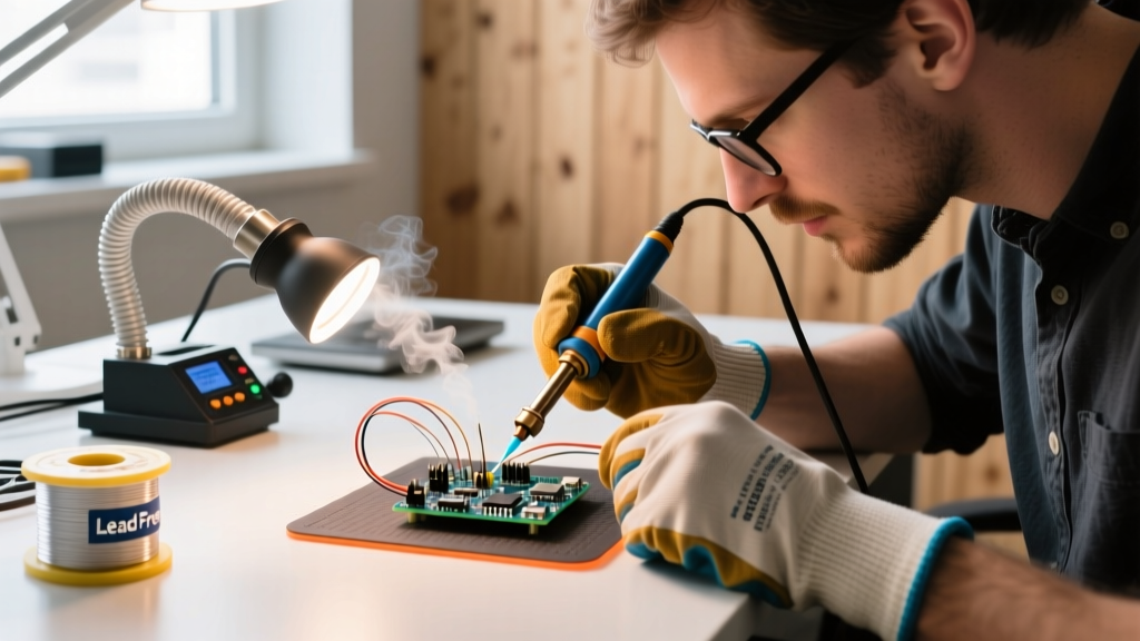
Place your pre-heated chisel tip so it bridges both the wire and the solder lug simultaneously. Feed the solder wire into the joint, not directly onto the iron tip. The solder should melt and wick into the wire strands and lug eyelet within 2 to 4 seconds. Remove the solder, then remove the iron.
Step 4: Cooling and Inspection
Allow the joint to cool naturally for 5 seconds. Do not blow on it, as rapid cooling can cause micro-fractures in the crystalline structure of the solder. A proper joint will be shiny (for leaded) or smoothly matte (for lead-free) and form a smooth fillet around the wire.
Pro-Tip for Audio Builders: If you are wiring a high-end audio selector switch, use a low-temperature soldering iron setting (300°C) and work quickly. Excessive heat can alter the contact resistance of the switch's internal silver-alloy wipers, introducing audible distortion or channel crosstalk in your signal path.
Troubleshooting Common Switch Soldering Failures
Even experienced technicians encounter issues when working with electromechanical components. Here is how to diagnose and fix the most common failures.
1. Melted or Warped Plastic Housing
The Cause: Dwell time exceeded 5 seconds, usually due to an underpowered iron, a dirty tip, or using a conical tip that failed to transfer heat efficiently to the heavy lug. The Fix: If the phenolic housing is melted near the terminal, the switch is compromised. Moisture and flux residue can now enter the internal contact chamber, leading to arcing. Discard the switch. Upgrade to a 60W+ station and a chisel tip for the replacement.
2. Internal Contact Welding (Switch Stuck 'ON')
The Cause: Heat traveled down the brass terminal and into the switch body, melting the internal insulating grease or warping the delicate contact leaf inside a microswitch or pushbutton. The Fix: Always use a heat sink clip on the terminal between your solder joint and the switch body. As noted in the E-Switch Technical FAQ, most miniature switches have a strict soldering temperature limit (typically 260°C for a maximum of 5 seconds) to prevent internal damage.
3. Cold Solder Joints on Spade Terminals
The Cause: Quick-connect spade terminals have massive thermal mass. If the solder looks dull, grainy, or forms a ball that refuses to wet the metal, the terminal did not reach the solder's liquidus temperature. The Fix: Pre-tin the spade terminal first. Apply flux, touch the iron to the spade until it is hot enough to melt the solder on contact, and coat it. Then, place your pre-tinned wire against the pre-tinned spade and apply heat briefly to fuse them together.
Frequently Asked Questions (FAQ)
Can I use heat shrink tubing over a soldered switch lug?
Yes, but you must allow the solder joint to cool completely to room temperature first. If you apply heat shrink while the terminal is still holding residual heat, the shrinking process can trap vaporized flux inside the tubing, which may become corrosive over time. Furthermore, applying a heat gun to a freshly soldered switch can easily push the internal temperature past the plastic's glass transition point, warping the housing.
Should I use liquid flux when soldering PCB-mount tact switches?
It is highly discouraged unless the switch is explicitly rated as 'flux-tight' or 'washable.' Standard tact switches are not hermetically sealed. Liquid flux can easily wick under the actuator button via capillary action, gumming up the internal snapping dome and causing the button to stick or fail to register clicks.
What is the best wire gauge for panel-mount toggle switches?
For standard 3A to 6A miniature toggles, 20 AWG or 22 AWG stranded silicone wire is ideal. It is flexible, preventing mechanical stress on the solder lug when routing wires behind a panel. For 15A heavy-duty rockers, use 14 AWG or 16 AWG wire to prevent voltage drop and resistive heating in the wire itself.