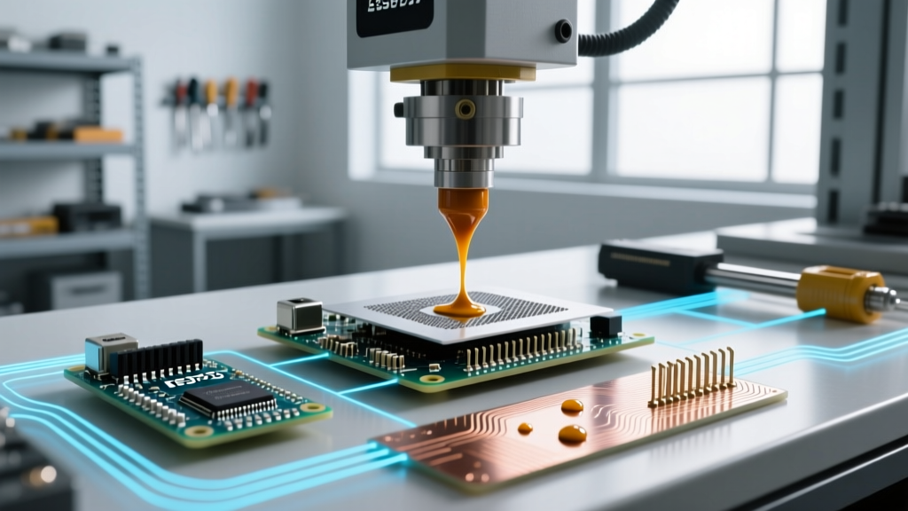

The Evolution of SMT: Why Paste Selection Dictates Yield
When scaling Surface Mount Technology (SMT) lines for 2026 production volumes, the selection of the correct paste for soldering is no longer a commoditized afterthought. As the electronics industry pushes toward 01005 (0.4mm x 0.2mm) passive components and micro-BGAs with 0.35mm pitch densities, the rheology, alloy composition, and flux chemistry of your solder paste directly dictate first-pass yield (FPY). A mismatch between stencil aperture design and solder powder mesh size can result in catastrophic defect rates, costing high-volume manufacturers thousands of dollars per hour in line downtime and rework.
This comprehensive guide dissects the technical parameters of industrial solder pastes, providing procurement engineers and process technicians with the data needed to optimize reflow profiles, select appropriate alloys for specific reliability sectors, and mitigate common SMT defects.
Decoding Solder Paste Alloys for High-Reliability Sectors
The transition away from tin-lead (SnPb) is largely complete in consumer electronics, but industrial, automotive, and aerospace sectors require nuanced alloy selections based on thermal cycling requirements and RoHS exemptions. In 2026, SAC (Tin-Silver-Copper) alloys remain the baseline, but doping elements like bismuth, nickel, and antimony are increasingly utilized to combat drop-shock failures and thermal fatigue.
| Alloy Designation | Composition (Weight %) | Solidus / Liquidus (°C) | Primary Industry Application | Approx. Cost per 500g Jar (2026) |
|---|---|---|---|---|
| SAC305 | Sn96.5 / Ag3.0 / Cu0.5 | 217°C / 220°C | Consumer, Commercial IT, Standard Automotive | $45 - $65 |
| SAC405 | Sn95.5 / Ag4.0 / Cu0.5 | 217°C / 221°C | High-Reliability Automotive (AEC-Q100) | $70 - $95 |
| Sn63Pb37 | Sn63 / Pb37 | 183°C / 183°C | Aerospace, Military (MIL-PRF-38535), Medical | $35 - $50 |
| BiSnAg (Low Temp) | Bi57.6 / Sn42 / Ag0.4 | 138°C / 138°C | Heat-sensitive sensors, LED assemblies | $85 - $110 |
| SAC305-Ni (Doped) | Sn96.5 / Ag3.0 / Cu0.5 / Ni0.05 | 217°C / 220°C | High-vibration environments, Drop-shock resistant | $60 - $80 |
For automotive control units subjected to under-hood thermal cycling (-40°C to +150°C), SAC405 or doped SAC alloys with trace nickel are preferred. The nickel doping inhibits the growth of the Cu6Sn5 intermetallic compound (IMC) layer, which can become brittle and fracture under mechanical stress. Conversely, for heat-sensitive optical sensors, BiSnAg low-temperature pastes prevent substrate warping, though they require specialized underfill to compensate for the inherent brittleness of bismuth.
Powder Mesh and Stencil Synergy: Type 4 vs. Type 5
The IPC J-STD-005 standard categorizes solder powder by mesh size. Selecting the correct powder type is a function of your smallest stencil aperture and the component pitch. As a rule of thumb, the stencil aperture width must accommodate at least five to six solder spheres across its span to ensure consistent print volume and prevent clogging.
- Type 3 (25–45 µm): The legacy workhorse. Ideal for standard SMT components down to 0402 (1005 metric) and QFPs with 0.5mm pitch. Rarely recommended for new 2026 high-density designs.
- Type 4 (20–38 µm): The current industry standard for advanced SMT. Required for 0201 passives, standard BGAs, and QFNs with 0.4mm pitch. Offers an optimal balance between print definition and paste shelf-life.
- Type 5 (10–25 µm): Essential for 01005 components, micro-BGAs (0.3mm pitch or less), and flip-chip CSPs. Type 5 pastes are highly susceptible to oxidation and require strict nitrogen-reflow environments and refrigerated storage.
- Type 6 (5–15 µm): Emerging in 2026 for advanced semiconductor packaging and wafer-level bumping. Rarely used in standard PCB assembly due to extreme slumping tendencies.
Flux Chemistry: Navigating IPC J-STD-004B Classifications
The flux vehicle within the paste for soldering serves three critical functions: it removes metal oxides, protects the joint from re-oxidation during reflow, and dictates the post-reflow residue characteristics. According to IPC standards, fluxes are classified by material (Rosin, Resin, Organic, Inorganic) and activity level.
Expert Insight: Never default to ROL0 (Rosin, Low activity, No-clean) for boards with heavy Oxide layers or ENIG finishes that have exceeded their shelf life. The mild activators in ROL0 will fail to clear the oxidation, resulting in non-wetting or de-wetting defects. Upgrade to ROM1 (Moderate activity) or utilize a water-soluble ORH1 formulation for power electronics where ionic residue must be aggressively washed to prevent electrochemical migration (dendritic growth).
The Stencil Area Ratio (AR) Imperative
Paste release from the stencil is governed by the Area Ratio, calculated as the area of the aperture opening divided by the area of the aperture sidewalls. For reliable transfer efficiency (TE > 85%), the AR must be strictly greater than 0.66. When printing Type 5 pastes for micro-BGAs, maintaining this ratio becomes physically challenging. In these scenarios, applying a nano-coating to the stencil (e.g., fluoropolymer-based hydrophobic coatings) reduces surface tension, allowing for aperture reductions of up to 20% while maintaining optimal paste release.
Reflow Profile Matching: RTS vs. RSS
The thermal profile applied in the reflow oven must be matched to the flux chemistry and the thermal mass of the PCB. Industry research highlighted by the Surface Mount Technology Association (SMTA) emphasizes that modern SAC305 pastes perform vastly differently under varying profile geometries.
- Ramp-to-Spike (RTS): A linear temperature increase from ambient to peak (235°C–245°C) with minimal dwell time above liquidus. This profile preserves flux activators, preventing them from exhausting before the solder melts. RTS is highly recommended for preventing "graping" and "head-in-pillow" defects in complex BGA components.
- Ramp-Soak-Spike (RSS): Features a distinct soak zone (150°C–180°C for 60–90 seconds) designed to equalize temperatures across a board with mixed thermal masses. While necessary for heavy copper power planes, the prolonged heat exposure can prematurely deplete the flux vehicle in standard SAC305 pastes, leading to severe oxidation and solder balling. If RSS is mandatory, specify a paste with high-thermal-stability resins and robust halogen-free activators.
Real-World Failure Modes and Mitigation Strategies
Even with premium materials from top-tier suppliers like Indium Corporation or MacDermid Alpha, process deviations cause distinct failure modes. Recognizing these defects allows for rapid root-cause analysis.
1. Head-in-Pillow (HiP) Defects
The Problem: The BGA sphere and the printed paste deposit melt independently and fail to coalesce, leaving a weak, fractured joint resembling a head resting on a pillow.
Root Cause: BGA coplanarity issues combined with insufficient paste volume or premature flux exhaustion.
Mitigation: Switch from Type 4 to Type 5 paste to increase the deposited volume without altering stencil thickness. Implement an RTS reflow profile to ensure flux activators remain viable until the absolute peak temperature is reached.
2. Graping and Solder Balling
The Problem: Small, unsolidified spheres of solder remain on the surface of the main joint, resembling a cluster of grapes.
Root Cause: Flux vehicle boils off or oxidizes before the solder powder particles can fully coalesce, often seen in 0201 components with high surface-area-to-volume ratios.
Mitigation: Reduce the stencil aperture size by 10-15% to limit the exposed surface area of the paste deposit during the pre-heat phase. Ensure the oxygen concentration in the reflow oven is strictly maintained below 500 ppm (preferably < 200 ppm for Type 5).
3. Tombstoning (Drawbridging)
The Problem: A passive component stands on one end during reflow.
Root Cause: Uneven wetting forces caused by asymmetrical pad heating or inconsistent paste volumes.
Mitigation: Implement home-plate or inverted-home-plate aperture designs to delay the wetting on the inner edges of the pads, balancing the surface tension forces as the solder transitions through the liquidus phase.
2026 Procurement Strategy: Cost vs. Yield Analysis
Procurement teams often attempt to reduce BOM costs by sourcing off-brand, low-cost solder pastes. However, in high-mix, high-volume SMT environments, the cost of the paste itself is negligible compared to the cost of line stoppages and X-ray inspection bottlenecks. A $20 savings per 500g jar is instantly negated if a single 0.4mm pitch BGA requires X-ray rework.
For 2026 production planning, mandate that paste vendors provide Lot-Specific Rheology Reports detailing viscosity (typically 160-220 Pa·s at 10 rpm) and tack life (minimum 8 hours for high-speed pick-and-place). Furthermore, require continuous print-life testing data. A premium paste for soldering should maintain consistent transfer efficiency for at least 8 to 12 hours of continuous stencil printing without requiring manual solvent additions or stencil wipes, ultimately securing your first-pass yield and protecting your bottom line.