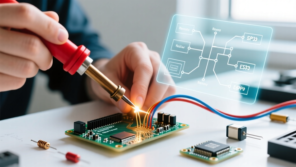

The Core Metallurgical Divide: Base Metal vs. Filler Metal
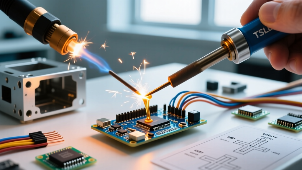
When evaluating the difference between welding and soldering, the fundamental distinction lies in the metallurgical behavior of the base materials. In welding, the base metals themselves are melted and fused together, often with the addition of a filler material, creating a continuous crystalline structure across the joint. In soldering, the base metals remain entirely solid; only the filler metal (the solder) is melted, relying on capillary action and metallurgical wetting to create a bond.
Understanding this divide is critical for DIYers, fabricators, and electronics hobbyists. Choosing the wrong process doesn't just result in a weak joint—it can lead to catastrophic structural failure, destroyed PCB traces, or melted insulation. This decision framework will guide you through the exact material, thermal, and mechanical parameters required to select the right joining method for your 2026 projects.
Decision Matrix: Welding vs. Soldering at a Glance
Before diving into the deep metallurgy, use this rapid-reference matrix to determine which process aligns with your project's baseline requirements.
| Parameter | Welding (MIG/TIG/Stick) | Soldering (Soft & Hard) |
|---|---|---|
| Base Metal Alteration | Melted and fused (Coalescence) | Remains solid (Surface wetting) |
| Typical Operating Temp | 2,500°F to 6,000°F+ (1,370°C - 3,300°C) | 360°F to 800°F (182°C - 426°C) |
| Joint Tensile Strength | 60,000 - 90,000+ PSI (Matches base metal) | 4,000 - 8,000 PSI (Dependent on filler) |
| Primary Application | Structural, load-bearing, high-stress | Electrical conductivity, plumbing seals, HVAC |
| Heat Affected Zone (HAZ) | Large; risks warping and brittleness | Minimal; risks pad delamination or insulation melt |
| Entry-Level Equipment Cost | $600 - $1,500 (e.g., Lincoln POWER MIG 210) | $150 - $350 (e.g., Hakko FX-951 Station) |
Deep Dive: When to Choose Welding
Welding is exclusively for applications requiring structural integrity and high mechanical load tolerance. When you weld mild steel using an ER70S-6 MIG wire, the resulting joint typically boasts a tensile strength of 70,000 PSI, effectively making the joint as strong as the parent material.
Real-World Applications & Edge Cases
- Automotive Chassis & Roll Cages: Requires deep penetration and structural certainty. TIG welding with ER308L stainless filler is the standard here to prevent micro-cracking in the Heat Affected Zone (HAZ).
- Heavy Machinery Brackets: MIG welding 1/4-inch steel plates. The high thermal input is necessary to achieve proper fusion, but it requires strict attention to joint beveling (typically a 60-degree V-groove) to avoid lack-of-fusion defects.
- Failure Mode to Avoid: Hydrogen-induced cracking (cold cracking). If welding high-carbon steels without pre-heating or using moisture-contaminated stick electrodes, hydrogen gets trapped in the cooling weld pool, causing delayed, catastrophic fractures.
Expert Insight: The biggest mistake DIYers make when welding thin sheet metal (under 18-gauge) is failing to manage thermal input. Excessive heat causes severe warping and burn-through. In these edge cases, pulse-MIG or TIG with a foot pedal amperage control is mandatory to keep the weld puddle frozen and precise.
Deep Dive: When to Choose Soldering
Soldering is the undisputed king of electrical connectivity and low-temperature fluid sealing. Because the base metal never reaches its melting point, you preserve the crystalline structure and temper of the parent materials. According to the IPC standards for electronics assembly, a proper solder joint relies on the formation of a precise Intermetallic Compound (IMC) layer—typically Cu6Sn5 when soldering to copper pads.
Material-Specific Soldering Frameworks
- PCB Electronics (Soft Soldering): Use SAC305 (96.5% Tin, 3.0% Silver, 0.5% Copper). This lead-free alloy melts at 217°C (423°F). Crucial Metric: Dwell time must be kept between 1.5 to 3 seconds per joint. Exceeding 5 seconds risks thermal pad lifting and excessive IMC overgrowth, which makes the joint brittle.
- Copper Plumbing (Hard Soldering/Sweating): Use 95/5 Tin-Antimony or Silver-bearing solder. Melting point hovers around 450°F. The joint relies entirely on capillary draw into a perfectly cleaned, fluxed slip-fit joint. If the copper isn't polished to bright shine with abrasive cloth, the flux cannot strip the copper oxide, resulting in a leak-path void.
- Stained Glass & Radiators: Traditional 60/40 Tin-Lead remains popular here for its low melting point (361°F) and superior wetting characteristics on large, heat-sinking surface areas.
The 'Grey Area': Brazing
If your project requires more strength than soft soldering can provide, but welding would melt the base material (such as joining copper refrigerant lines in HVAC systems), you enter the realm of brazing. Brazing uses filler metals that melt above 840°F (450°C)—commonly a 15% Silver-Phosphorus-Copper alloy (BCuP-5). It provides immense shear strength and vibration resistance without compromising the temper of the copper tubing.
The 4-Step Shop Floor Decision Flowchart
When standing in your shop holding two pieces of metal, run them through this sequential decision framework to finalize your joining method.
Step 1: Define the Joint's Primary Mission
Is the joint primarily load-bearing (supporting physical weight, torque, or impact) or functional (conducting electricity, sealing fluid, or transferring low-stress heat)? If load-bearing, default to welding or mechanical fastening. If functional, default to soldering or brazing.
Step 2: Audit the Thermal Limits of the Assembly
Look beyond the base metal. Are there PVC insulation jackets, plastic connectors, or heat-sensitive semiconductor components within 2 inches of the joint? Welding's radiant and conductive heat will destroy these. If thermal limits are strict, soldering (with localized heat sinking using aluminum tape or hemostats) is your only thermal-joining option.
Step 3: Evaluate Material Thickness and Conductivity
Joining two 12-AWG copper wires? Soldering with a 60W iron and rosin-core is perfect. Joining two 2/0 AWG battery cables? The massive thermal mass of the copper will act as a heat sink, pulling heat away from a standard soldering iron before the flux can activate, resulting in a cold joint. For high-mass copper, you must use a high-wattage soldering gun (like the Weller D550 at 260W) or switch to mechanical crimping with adhesive-lined heat shrink.
Step 4: Assess Post-Process Environmental Exposure
Will the joint be exposed to high-vibration environments (like a motorcycle frame) or corrosive marine salt spray? Welded steel will require immediate slag removal and passivation/painting to prevent rust. Soldered electrical joints in marine environments must be sealed with marine-grade adhesive heat shrink to prevent galvanic corrosion between the tin solder and copper wire, a phenomenon well-documented by the American Welding Society (AWS) in mixed-metal corrosion studies.
Final Verdict: Matching Process to Purpose
The difference between welding and soldering is not merely a matter of temperature; it is a fundamental choice between structural fusion and surface adhesion. By applying this decision framework, you eliminate guesswork. Respect the thermal limits of your components, understand the tensile requirements of your load paths, and select the precise alloy and equipment model required to execute a joint that will outlast the project itself.