
The Thermodynamics of Soldering: Why Dial Settings Lie
When technicians search for the ideal temp for soldering electronics, they frequently confuse the station's digital readout with the actual thermal energy transferred to the PCB pad. A soldering station set to 350°C does not instantly deliver 350°C to the joint. The moment the tip contacts a copper ground plane, the localized temperature plummets. What matters is not just the idle temperature, but the thermal recovery rate—measured in Watts and Joules—dictated by the station's heater core and tip geometry.
According to the IPC J-STD-001 standards for soldered electrical assemblies, the goal is to reach the solder's liquidus temperature plus a specific superheat margin, without exceeding the thermal degradation threshold of the component or PCB laminate. In 2026, with the widespread adoption of dense, multi-layer HDI (High-Density Interconnect) boards, managing this thermal delta is more critical than ever.
Master Temperature Matrix: Alloys & Applications
The correct temperature depends heavily on your solder alloy's melting point (liquidus) and the thermal mass of your target joint. Below is the definitive matrix for modern electronics workbench setups.
| Solder Alloy | Melting Point | Recommended Tip Temp | Max Dwell Time | Primary Use Case |
|---|---|---|---|---|
| Sn63/Pb37 (Leaded) | 183°C | 300°C - 330°C | 2 - 3 Seconds | Prototyping, vintage repair, hobbyist |
| SAC305 (Lead-Free) | 217°C - 220°C | 350°C - 380°C | 2 - 4 Seconds | Commercial production, RoHS compliance |
| Sn42/Bi57 (Low-Temp) | 138°C | 220°C - 250°C | 1 - 2 Seconds | Heat-sensitive sensors, flexible PCBs |
| Sn96.5/Ag3/Cu0.5 | 217°C | 350°C - 370°C | 3 Seconds | High-reliability automotive/aerospace |
Leaded vs. Lead-Free: Adjusting Your Thermal Profile
The Leaded Baseline (Sn63/Pb37)
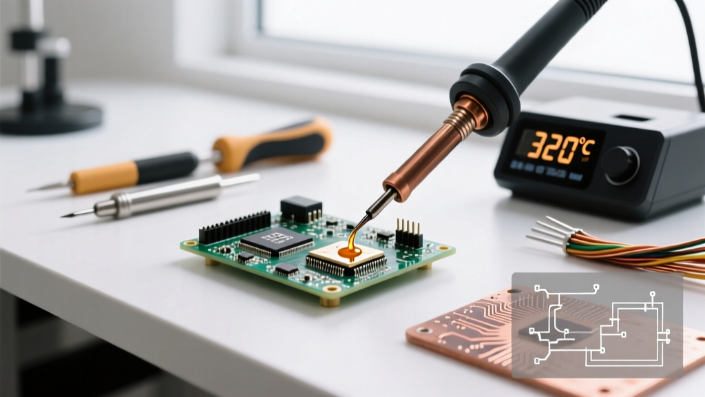
Eutectic tin-lead solder remains the gold standard for rework and DIY electronics due to its sharp 183°C melting point and excellent wetting characteristics. For standard through-hole and 0805 SMD components, setting your station to 320°C provides the ideal 137°C superheat. This ensures rapid flux activation and capillary flow without scorching the rosin core.
The Lead-Free Challenge (SAC305)
SAC305 (Tin-Silver-Copper) requires a minimum of 217°C to liquefy. However, lead-free fluxes require higher activation temperatures. If you set your iron to 250°C, the tip will drop below the liquidus point upon contact, resulting in a disturbed or cold joint. Professionals set their irons to 360°C for SAC305. The caveat? Higher temperatures accelerate tip oxidation. In 2026, premium stations mitigate this by utilizing localized inductive heating or integrated cartridge heaters that only draw power when thermal drop is detected, preserving tip life.
Component-Specific Thermal Limits: Avoiding Catastrophe
Knowing the temp for soldering electronics is only half the battle; knowing what your components can survive is the other. The NASA Electronic Parts and Packaging (NEPP) Program outlines strict thermal profiles for high-reliability hardware. Here are the critical limits for common components:
- MLCCs (Multi-Layer Ceramic Capacitors): Highly susceptible to thermal shock and flex cracking. The maximum temperature gradient should not exceed 2°C to 4°C per second. For sizes larger than 1206, localized pre-heating (using a hot air gun at 150°C) is mandatory before applying a 320°C iron tip to prevent micro-fractures.
- Electrolytic Capacitors: Prolonged heat causes the internal electrolyte to vaporize, leading to venting or catastrophic explosion. Limit tip contact to under 3 seconds at 330°C. Keep the iron tip at least 2mm away from the PVC sleeve.
- Plastic Connectors (JST, Molex): The PBT or Nylon housings typically have a heat deflection temperature around 260°C. Using a chisel tip at 380°C will melt the pin housing, causing pins to back out or short. Use a micro-pencil tip at 310°C and apply heat only to the metal pad.
- RF Shields and Ground Planes: Large copper pours act as massive heat sinks. Attempting to solder a ground pin with a standard 40W iron will result in a cold joint. Switch to a high-thermal-mass bevel tip or use a pre-heater bed set to 120°C to reduce the thermal delta.
2026 Soldering Station Thermal Recovery Showdown
To maintain the correct temperature under load, your hardware must possess rapid thermal recovery. Here is how the top-tier 2026 workbench stations compare:
| Station Model | Heater Technology | Recovery Speed | 2026 Street Price | Best For |
|---|---|---|---|---|
| JBC CD-2B | Integrated Cartridge | < 2 Seconds | $585 | Micro-SMD, heavy ground planes |
| Weller WX2021 | Smart Sensor / Inductive | < 4 Seconds | $650 | Production environments, IoT |
| Hakko FX-951 | Induction / Ceramic | ~ 6 Seconds | $320 | General through-hole, budget pro |
For deep-dive technical training on tip geometry and thermal transfer efficiency, the Hakko e-Learning portal provides excellent visual breakdowns of how chisel, conical, and bevel tips interact with varying pad sizes.
Troubleshooting Temperature-Induced Defects
Pro Tip: If your solder balls up on the tip and refuses to flow onto the pad, your iron is likely too hot (burning the flux instantly) or your tip is oxidized. Never use sandpaper to clean a tip; use a damp brass sponge and a tip-tinner compound.
Cold Joints (Dull, Grainy Appearance)
Cause: Iron temperature too low, insufficient dwell time, or moving the component before the solder solidifies. The alloy did not reach its liquidus point plus superheat.
Fix: Increase station temp by 20°C, use a wider tip to increase surface area contact, and apply flux to lower the surface tension.
Lifted Pads and Scorched FR4
Cause: Iron temperature set above 400°C, or dwelling on the pad for more than 5 seconds. The adhesive bonding the copper to the FR4 fiberglass degrades, causing delamination.
Fix: Lower the temperature to 350°C. If the pad isn't taking heat, the issue is likely oxidation on the pad, not a lack of iron heat. Clean with isopropyl alcohol and apply fresh No-Clean flux.
Frequently Asked Questions
What is the safest temp for soldering electronics for beginners?
For beginners using standard 63/37 leaded solder on through-hole kits, set your station to 320°C (608°F). This provides a forgiving window that melts the solder quickly without instantly burning the flux or melting plastic DIP sockets.
Does higher temperature make soldering faster?
No. Cranking your station to 450°C will not transfer heat faster; it will only oxidize your tip in minutes and burn the flux before it can clean the joint. Thermal transfer is dictated by tip mass and surface area contact, not just peak temperature. A thick chisel tip at 330°C will solder a large joint faster than a micro-conical tip at 400°C.
How do I know if my iron's temperature calibration is off?
Use a digital tip thermometer (like the Hakko FG-100B). Place the sensor on the tip with a drop of solder to ensure thermal coupling. If the reading deviates by more than ±5°C from your station's display, run the station's internal calibration offset routine.