
The Evolution of Auto Soldering for Small-Batch and DIY
For decades, automated soldering was strictly confined to massive surface-mount technology (SMT) lines and high-volume contract manufacturing. However, as we navigate through 2026, the landscape has shifted dramatically. Desktop Cartesian robots, smart automated solder feeders, and vision-guided systems have democratized auto soldering, bringing industrial-grade repeatability to small-batch PCBA (Printed Circuit Board Assembly) facilities, advanced DIYers, and boutique hardware startups. But with capital costs ranging from $300 for automated feeders to over $5,000 for fully integrated desktop robotics, how do you choose the right system?
To answer this, we convened a panel of three industry experts to dissect the current state of auto soldering hardware, thermal management edge cases, and return on investment (ROI) metrics.
Meet the Expert Panel
- Dr. Aris Thorne: Senior PCBA Process Engineer with 15 years in mixed-technology assembly and IPC certification instruction.
- Elena Rostova: High-volume hardware creator and YouTube educator specializing in open-source manufacturing and DIY CNC integrations.
- Marcus Vance: Robotics Integrator focusing on benchtop automation, machine vision, and soldering metallurgy for boutique electronics firms.
Hardware Comparison Matrix: 2026 Auto Soldering Systems
Before diving into the nuances of thermal profiling and flux chemistry, it is critical to understand the baseline capabilities and costs of the three dominant auto soldering categories available today.
| System Category | Representative Model (2026) | Capital Cost | Avg. Cycle Time | Maintenance Overhead | Best Use Case |
|---|---|---|---|---|---|
| Cartesian Desktop Robot | Apollo Seiko L-Station | $4,200 - $5,500 | 2.5s / joint | High (Tip/N2 calibration) | Complex SMD/Mixed, High-Mix Low-Volume |
| Automated Solder Feeder | Hakko 374 / 373 Series | $280 - $320 | Manual (4s / joint) | Low (Clearing wire jams) | High-Volume Through-Hole (TH) |
| DIY CNC Solder Rig | Custom Marlin/Klipper Mod | $800 - $1,200 | 4.0s / joint | Extreme (Firmware tuning) | Prototyping, Educational Labs |
Deep Dive: Cartesian Desktop Robotics
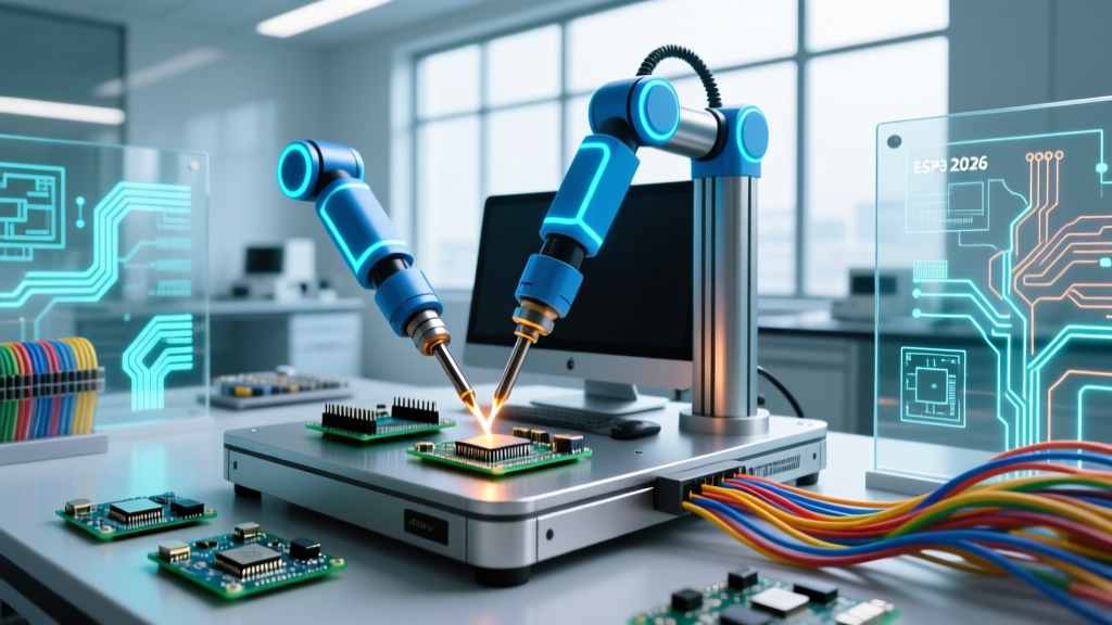
When engineers refer to true benchtop auto soldering, they are usually talking about Cartesian desktop robots like the Apollo Seiko L-Station or the Janome JR3000 series. These systems utilize CCD machine vision to locate fiducial markers, automatically correcting for X-Y-Z offsets caused by warped PCBs or imperfect fixture placement.
The Vision and Precision Advantage
Marcus Vance highlights the necessity of vision systems in modern auto soldering: 'In 2026, relying on blind coordinate programming is a recipe for Z-axis crashes. A 0.5mm warp in a 4-layer FR4 board will cause a blind robot to crush a 0402 capacitor or fail to make contact with a fine-pitch QFP pad. The Apollo Seiko's laser displacement sensors and CCD cameras map the topography of the board in real-time, adjusting the Z-height dynamically within a 0.02mm tolerance.'
'The biggest failure mode in desktop auto soldering isn't the robot's precision; it's thermal management. A standard 60W iron on a Cartesian arm will fail to wet a heavy ground plane because the dwell time is fixed, unlike a human who intuitively holds the tip longer to absorb the thermal mass.'
— Dr. Aris Thorne, PCBA Process Engineer
Edge Case: Thermal Lag and Nitrogen Integration
Dr. Thorne's observation points to a critical edge case in robotic soldering: thermal lag. When a robot dispenses 0.8mm SAC305 (Tin-Silver-Copper) solder wire onto a via connected to an internal ground plane, the plane acts as a massive heat sink. If the robot's dwell time is hardcoded to 1.5 seconds, the solder will ball up and fail to wet, resulting in a cold joint.
To combat this, experts mandate the use of Nitrogen (N2) generators integrated into the auto soldering head. By flooding the soldering zone with N2 at a flow rate of 400-600 cc/min, the oxidation of the iron tip is virtually eliminated. This ensures maximum thermal transfer efficiency, allowing a 150W cartridge heater (like the Hakko T18 or Apollo equivalents) to recover temperature in milliseconds between joints.
Deep Dive: Automated Solder Feeders (The Semi-Auto Workhorse)
For operations where full Cartesian automation is cost-prohibitive, automated solder feeders represent the most pragmatic entry into auto soldering. The Hakko 374 remains the undisputed king of this category in 2026, priced affordably around $290.
How Automated Feeders Change the Workflow
An automated feeder does not move the iron; it moves the solder. By using a foot pedal or a proximity sensor, the operator triggers the feeder to push a precise length of flux-cored solder wire (typically measured in 0.1mm increments) directly to the tip of the iron.
- Consistency: Eliminates the 'too much solder' bridge on SOIC-8 pins or the 'too little solder' starved joint on power terminals.
- Ergonomics: Frees up the operator's non-dominant hand to hold down wires or manipulate the PCB, reducing repetitive strain injuries (RSI).
- Speed: In high-volume through-hole environments, operators report a 25-30% increase in throughput when using a foot-pedal-activated Hakko 374 compared to manual wire feeding.
Failure Modes to Watch
Elena Rostova warns about the hidden pitfalls of automated feeders: 'The most common failure mode I see in maker spaces is wire jamming due to oxidized solder. If you leave a spool of Sn63/Pb37 or SAC305 exposed to high humidity for months, the flux core can degrade, and the outer alloy can develop a microscopic oxide layer. This increases friction inside the PTFE guide tube, causing the feeder's stepper motor to slip and resulting in inconsistent solder volumes.'
Metallurgy and Flux Chemistry in Automated Systems
Auto soldering systems are entirely dependent on the consumables fed into them. You cannot use cheap, no-name solder wire in a $5,000 Apollo Seiko robot and expect IPC-compliant results.
Choosing the Right Wire Diameter and Flux Core
For automated dispensing, the solder wire diameter must be matched to the joint volume. Over-dispensing 1.0mm wire onto a 0603 SMD pad will cause the flux to boil violently, creating solder splatter that contaminates the robot's vision lens and the PCB's conformal coating zones.
| Component Type | Recommended Wire Diameter | Flux Classification (IPC J-STD-004) | Typical Robot Feed Rate |
|---|---|---|---|
| 0402 / 0603 SMD | 0.3mm - 0.5mm | ROL0 (Rosin, Low Activity, No Halides) | 5mm - 10mm / sec |
| SOIC / QFP / TH Small | 0.6mm - 0.8mm | ROL1 (Rosin, Low Activity, Mild Halides) | 15mm - 25mm / sec |
| Power Terminals / Large TH | 1.0mm - 1.5mm | REL1 (Resin, Low Activity) | 30mm - 50mm / sec |
According to the IPC J-STD-001 Requirements for Soldered Electrical and Electronic Assemblies, the selection of flux activity must balance the need for wetting on slightly oxidized pads against the risk of post-assembly corrosion. In automated systems where post-solder cleaning is often skipped (using No-Clean fluxes), ROL0 is the mandatory standard to prevent electrochemical migration (dendrite growth) in high-impedance circuits.
Quality Assurance and IPC Standards
Implementing auto soldering does not exempt a workshop from rigorous quality control. In fact, automated systems require stricter baseline profiling because a single misconfigured parameter (like a Z-axis offset of 0.5mm) will replicate the exact same defective joint 500 times before an operator notices.
Validating Automated Joints
Dr. Thorne insists on regular validation against the IPC-A-610 Acceptability of Electronic Assemblies standard. Key inspection criteria for robotic soldering include:
- Fillet Geometry: Automated systems tend to create highly symmetrical, sometimes overly convex fillets due to fixed retraction speeds. Inspectors must ensure the solder wets the pad and lead at an angle of less than 90 degrees, indicating proper intermetallic compound (IMC) formation.
- Flux Residue Entrapment: Because robots dispense solder rapidly, flux can sometimes boil and trap gas bubbles inside the fillet, leading to blowholes. Cross-section X-ray analysis is recommended during the initial setup phase of a new PCBA run.
- Tip Wear Artifacts: As the iron tip's iron-plating layer degrades, it can leave microscopic iron inclusions in the solder joint. Adhering to the NASA Workmanship Standard for Soldered Connections requires immediate tip replacement if pitting or dewetting is observed on the tip surface, a common issue in high-cycle auto soldering environments.
The Final Verdict: Calculating Your ROI
So, is auto soldering worth the investment for your workbench or small-batch facility in 2026?
When to Buy an Automated Solder Feeder
If your primary workload consists of through-hole components, wire harnesses, or large-pitch SMD connectors, the Hakko 374 is a no-brainer. At ~$300, the ROI is realized within the first 50 hours of labor saved through increased speed and reduced solder waste. It is the ultimate 'force multiplier' for manual assembly.
When to Invest in Cartesian Desktop Robotics
If you are assembling high-density mixed-technology boards (e.g., 0402 passives alongside 0.5mm pitch BGAs) in batches of 50 to 500 units, a Cartesian robot like the Apollo Seiko L-Station is essential. While the $4,500+ entry price and mandatory nitrogen infrastructure represent a significant hurdle, the elimination of human-induced variability, coupled with the ability to run the machine unattended (lights-out manufacturing for small batches), yields a positive ROI typically within 8 to 14 months for contract manufacturers.
Ultimately, auto soldering in 2026 is no longer about replacing the human touch; it is about augmenting human capability, ensuring metallurgical consistency, and scaling production without sacrificing the rigorous standards demanded by modern electronics.