
The True Cost of Compromised Audio Connections
In the modern pro audio landscape of 2026, where immersive formats like Dolby Atmos demand dozens of discrete analog channels, the reliability of your physical layer is non-negotiable. Soldering XLR connectors seems like a fundamental skill, yet the difference between a tour-ready termination and a failure-prone joint lies in a series of micro-decisions. A single cold joint or shield short on a multicore snake can halt a live broadcast or ruin a studio tracking session. This decision framework strips away generic advice, providing exact specifications, thermal profiles, and component matrices to ensure your XLR terminations meet rigorous IPC and broadcast standards.
Decision 1: Selecting the XLR Chassis and Contact Geometry
Not all XLR connectors are engineered equally. The physical design of the solder cups, the strain relief mechanism, and the contact plating dictate both your soldering workflow and the long-term oxidation resistance of the joint. When specifying connectors for professional audio wiring, you are primarily choosing between three industry stalwarts: Neutrik, Amphenol, and Switchcraft.
| Brand & Model | Solder Cup Design | Cable OD Range | Avg. Price (2026) | Best Application |
|---|---|---|---|---|
| Neutrik NC3MXX / NC3FXX | Deep, narrow cups with capillary action | 3.5 - 8.0 mm | $4.50 - $6.00 | Touring, high-vibration environments |
| Amphenol AC3M / AC3F | Wide, shallow cups, easy access | 3.5 - 7.5 mm | $2.50 - $3.50 | Studio patchbays, bulk installations |
| Switchcraft 114B / 112B | Flat solder lugs (requires crimping/folding) | 4.0 - 8.5 mm | $5.00 - $7.00 | Military, vintage gear restoration |
The Verdict on Connector Selection
For 90% of professional applications, the Neutrik XX series remains the gold standard. Its chuck-style strain relief grips the outer jacket symmetrically, preventing torque from transferring to the solder cups. However, the deep solder cups require precise wire trimming (exactly 3mm of exposed conductor) to prevent solder wicking up the wire and creating a brittle fracture point just outside the cup.
Decision 2: Solder Alloy and Flux Core Selection
The metallurgical bond between the copper conductor and the nickel/silver-plated XLR cup is governed by your solder choice. While consumer electronics have largely transitioned to lead-free alloys due to RoHS directives, professional audio wiring still heavily favors leaded eutectic alloys for their superior flexibility and lower melting points, which reduce thermal stress on delicate cable insulation.
- Kester 44 (Sn63/Pb37) - 0.031 inch: The undisputed workhorse. The 63/37 ratio is eutectic, meaning it transitions from liquid to solid instantly without a plastic (mushy) state, virtually eliminating cold joints caused by micro-movements during cooling. The 331 rosin flux core (2.2%) provides excellent wetting on nickel-plated Neutrik cups.
- SAC305 (Sn96.5/Ag3.0/Cu0.5) - 0.031 inch: The lead-free alternative. Requires higher temperatures and yields a stiffer, more brittle joint. Not recommended for touring cables subjected to constant coiling and bending, but acceptable for fixed studio installations where RoHS compliance is mandated.
- Sn62/Pb36/Ag2 (2% Silver Bearing): Ideal for audio connectors with heavy silver plating. The silver content prevents the solder from leaching the silver plating off the contact surface (a phenomenon known as silver scavenging), preserving the connector's low-contact-resistance properties over decades.
Expert Insight: Never use plumbing solder or acid-core flux on audio wiring. Acid flux will rapidly corrode the copper strands, turning them green and brittle within months, leading to intermittent signal dropouts that are nearly impossible to trace. Always stick to rosin-based (RMA) flux cores.
Decision 3: Thermal Profiling and Tip Geometry
Soldering XLR cups requires a delicate thermal balance. The cups act as massive heat sinks compared to standard PCB pads. If your iron lacks the thermal recovery to maintain temperature, you will apply the iron for too long, melting the inner dielectric insulation of the cable and causing a short between the signal core and the shield.
Optimal Temperature Matrix
According to IPC J-STD-001 soldering standards, dwell time should be minimized. For XLR terminations, aim for a 2 to 3-second maximum dwell time per cup.
- For 63/37 Leaded Solder: Set station to 350°C (662°F).
- For SAC305 Lead-Free: Set station to 380°C (716°F).
- For Silver-Bearing Alloys: Set station to 360°C (680°F).
Tip Selection: Bevel vs. Chisel
Discard the standard D24 chisel tip for XLR work. The optimal geometry is a B3 or B4 Bevel (Hoof) tip. The concave curve of the bevel tip cradles the rounded exterior of the XLR solder cup, maximizing surface area contact and allowing the molten solder to flow via capillary action directly into the wire insertion hole. A chisel tip only contacts the cup on a flat edge, leading to uneven heating and a higher risk of bridging adjacent pins on tight 3-pin layouts.
The Execution Framework: Step-by-Step Termination
Consistency in physical preparation is just as critical as thermal management. When working with premium quad-core or dual-core shielded cables like Mogami W2549 or Belden 8412, follow this exact dimensional framework:
- Jacket Stripping: Remove exactly 20mm of the outer PVC/rubber jacket. Do not nick the braided shield.
- Shield Preparation: Twist the braided shield tightly into a single pigtail. For Neutrik connectors, trim the shield pigtail to 6mm. Tin the shield immediately with a 1-second touch of the iron to prevent fraying.
- Dielectric Stripping: Strip exactly 3mm of the inner Teflon/PVC insulation from the hot (Pin 2) and cold (Pin 3) conductors. Crucial: If you expose more than 3mm, the bare wire risks touching the adjacent pin or the metal chassis, causing a short.
- Pre-Tinning: Tin the 3mm exposed conductors. The solder should wick to the insulation edge but not bulge. The wire must remain perfectly cylindrical to fit into the Neutrik cup.
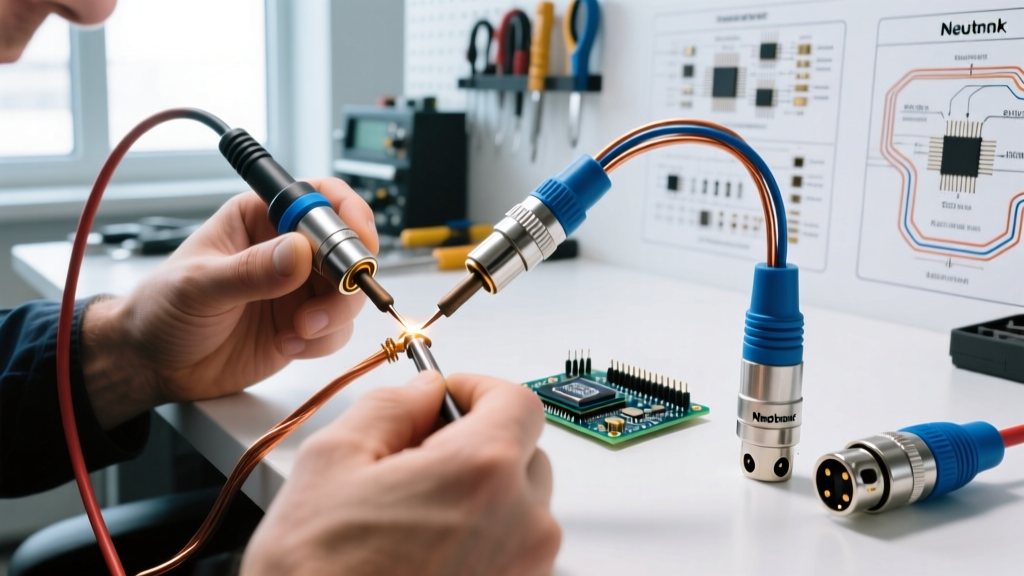
- Cup Loading: Apply a microscopic amount of fresh solder to the empty XLR cup (tinning the cup). Insert the pre-tinned wire. Apply the bevel tip to the outside of the cup for 1.5 seconds. The solder should melt and flash smoothly around the wire entry point, forming a concave fillet.
- Inspection: Verify the balanced audio wiring pinout (Pin 1: Ground, Pin 2: Hot, Pin 3: Cold) before the shell is screwed on. Look for dull, grainy textures (cold joints) or excessive solder doming (bridging risk).
Failure Mode Analysis and Edge Cases
Even experienced technicians encounter edge cases when soldering XLR connectors in the field. Recognizing these failure modes allows for immediate course correction.
1. The 'Mushroom' Solder Joint
Symptom: A large, bulbous ball of solder sits on top of the cup, obscuring the wire entry point. Cause: Over-application of solder wire, or the wire was not pre-tinned and seated fully into the cup before applying heat. Fix: Use solder wick (desoldering braid) to remove the excess. A proper joint should be concave, revealing the outline of the wire entering the cup.
2. Insulation Melt-Back
Symptom: The inner dielectric insulation shrinks back from the cup, exposing bare wire that threatens to short against the shell. Cause: Dwell time exceeded 4 seconds, or the iron temperature was set too low, forcing the technician to hold the iron in place longer to achieve flow. Fix: Increase station temperature by 20°C and use a larger thermal mass tip (B4 instead of B2) to transfer heat instantly.
3. Strain Relief Slippage
Symptom: The cable pulls out of the connector shell under tension, tearing the solder joints. Cause: The outer jacket was stripped too far back, meaning the connector's chuck-style strain relief is clamping down on the delicate inner signal wires and shield rather than the thick outer PVC jacket. Fix: Always ensure the strain relief clamp bites exclusively into the primary outer jacket. If the cable OD is too small for the connector, use the included polyamide insertion bushing (common in Neutrik XX kits) to take up the slack.
Final Thoughts on Audio Wiring Integrity
Soldering XLR connectors is an exercise in applied metallurgy and precision mechanics. By treating the process as a series of deliberate decisions—selecting the correct deep-cup chassis, utilizing eutectic 63/37 solder with a rosin core, and deploying a bevel tip at exactly 350°C—you transition from merely 'making connections' to engineering failure-proof signal paths. In high-stakes audio environments, the time invested in mastering this framework pays dividends in absolute signal integrity and long-term mechanical resilience.