
Decoding Soldering Rings: Splices vs. Preforms
When electrical engineers, marine DIYers, and PCB designers search for "soldering rings," they are typically referring to one of two entirely different components. In wiring and automotive applications, the term refers to solder ring splices (commonly known as heat shrink solder sleeves). In electronics manufacturing and heavy-duty terminal lugging, it refers to solder preform rings (stamped solder washers). Both serve to create robust, low-resistance electrical connections, but their application methods, thermal profiles, and failure modes are vastly different.
This comprehensive FAQ and troubleshooting guide breaks down the exact specifications, common failure modes, and technical fixes for both types of soldering rings, ensuring your connections meet rigorous industry standards in 2026.
Part 1: Solder Ring Splices (Heat Shrink Sleeves)
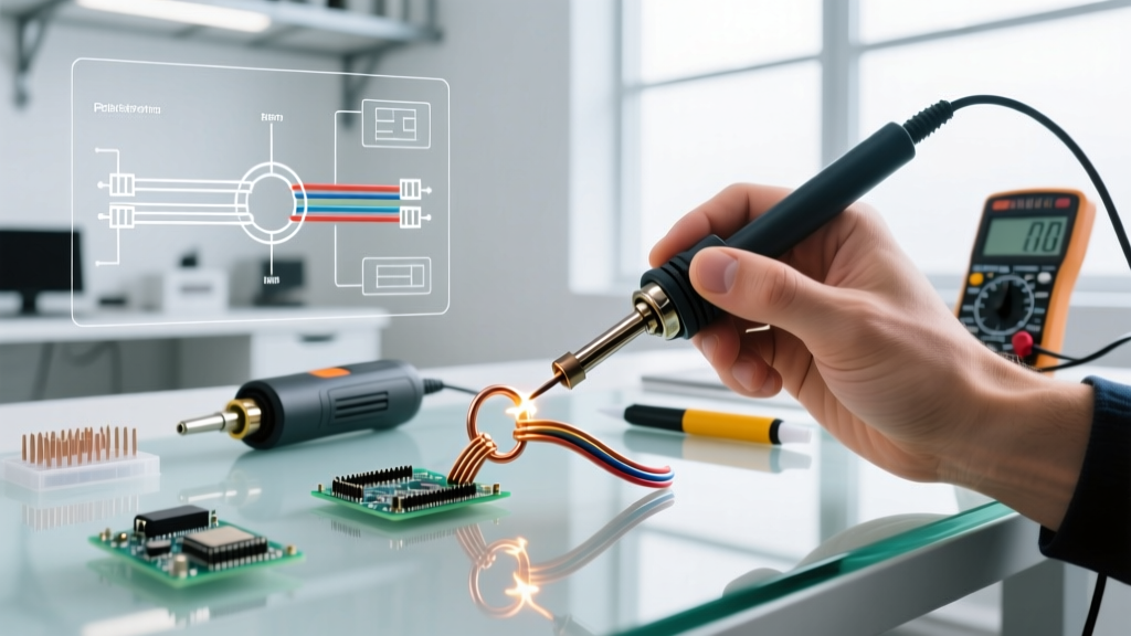
Solder ring splices are dual-walled tubing components featuring a polyolefin outer jacket, a thermoplastic sealant inner layer, and a preform ring of flux-cored solder in the center. They are the gold standard for creating waterproof, vibration-resistant inline wire splices in marine, automotive, and aerospace environments.
FAQ: Sizing and Color Codes
Using the wrong size splice is the leading cause of splice failure. The solder ring must make direct, tight contact with the twisted wire strands to ensure proper thermal transfer and capillary flow. Below is the standard AWG-to-color mapping used by major manufacturers like TE Connectivity (Raychem) and 3M.
| Jacket Color | Wire Gauge (AWG) | Cross-Section (mm²) | Typical Application |
|---|---|---|---|
| Clear / White | 22 - 18 AWG | 0.34 - 0.82 | Sensors, low-current ECU wiring |
| Blue | 16 - 14 AWG | 1.31 - 2.08 | Lighting circuits, 12V accessories |
| Red | 12 - 10 AWG | 3.31 - 5.26 | Fuel pumps, high-draw relays |
| Yellow | 8 - 6 AWG | 8.37 - 13.30 | Winches, marine battery banks |
Troubleshooting Solder Ring Splice Failures
Even with the correct sizing, improper thermal application will ruin the joint. Here is how to diagnose and fix the most common issues encountered in the field.
1. Solder Beading or Refusal to Flow (Cold Joint)
- Root Cause: Insufficient heat reaching the solder ring, or severe oxidation on the copper wire strands preventing the flux from activating.
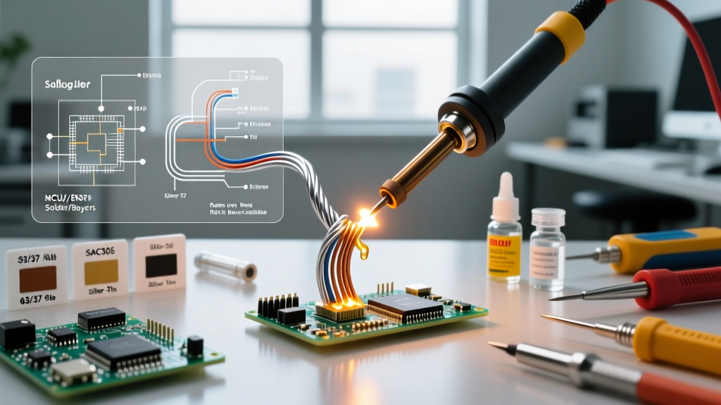
- Technical Fix: Never use a butane lighter; it causes localized scorching and deposits soot that inhibits wetting. Use a calibrated heat gun (e.g., Master HG-501B or Hakko 881D) set between 250°C and 300°C. If the wire is oxidized, lightly abrade the strands with a fiberglass scratch pen before twisting and inserting them into the sleeve. The polyolefin shrinks at ~120°C, but the Sn63/Pb37 solder ring requires 183°C to reach liquidus. You must push past the shrink temperature to melt the solder.
2. Thermoplastic Sealant Blowout
- Root Cause: Overheating the center of the splice before the ends have sealed, causing the inner adhesive to boil and push out the ends, taking flux with it.
- Technical Fix: Apply heat starting from the center to tack the wires, but immediately move the heat gun in a circular motion toward the outer edges. This forces the sealant to flow outward toward the wire jackets, creating a watertight environmental seal without boiling out the flux core.
3. Burnt or Brittle Polyolefin Jacket
- Root Cause: Holding a high-wattage heat gun stationary on one spot for more than 4-5 seconds.
- Technical Fix: Keep the heat gun moving at a distance of 2 to 3 inches. If working in tight engine bays, use a reflective heat shield tape (like Kapton or aluminum foil tape) wrapped around adjacent wiring to prevent collateral thermal damage.
Part 2: Solder Preform Rings (PCB & Terminal Washers)
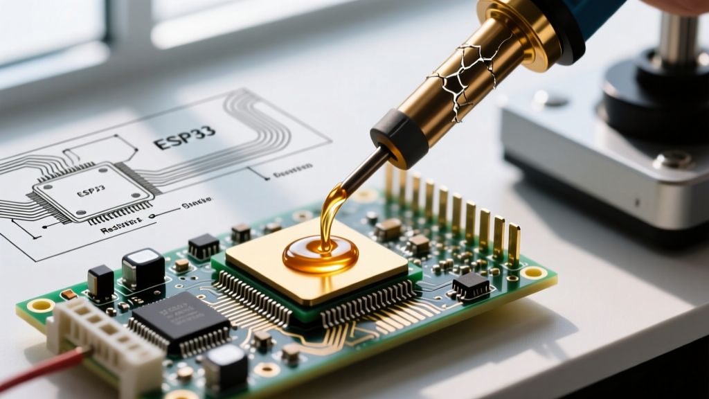
Solder preform rings are precisely stamped washers made from specific solder alloys. They are placed over component leads or terminal pins before reflow or iron soldering. They eliminate the variability of manual solder wire feeding, ensuring exact volumetric deposition for high-reliability joints.
FAQ: Alloy Selection and Volumetric Calculation
Choosing the right alloy and volume is critical. According to workmanship requirements outlined by NASA's Electronic Parts and Packaging (NEPP) program, the solder fillet must be visually verifiable and meet specific concave profiles.
| Alloy Designation | Composition | Melting Point (Liquidus) | Primary Use Case |
|---|---|---|---|
| Sn63/Pb37 | 63% Tin, 37% Lead | 183°C (Eutectic) | Aerospace, legacy repair, high-reliability |
| SAC305 | 96.5% Sn, 3.0% Ag, 0.5% Cu | 217°C - 220°C | Commercial RoHS-compliant PCB assembly |
| Sn96.5/Ag3.5 | 96.5% Tin, 3.5% Silver | 221°C (Eutectic) | High-temperature automotive under-hood |
How to calculate the required ring volume:
To ensure a proper fillet without bridging adjacent pads, calculate the volume of the preform ring using the formula: V = π × h × (R² - r²), where h is the thickness, R is the outer radius, and r is the inner radius. A general rule of thumb for pin-in-hole terminals is that the preform volume should be 1.5x the calculated volume of the empty space in the plated through-hole (PTH) barrel.
Troubleshooting Preform Ring Failures
1. Insufficient Fillet (Starved Joint)
- Root Cause: The preform ring volume was miscalculated, or the flux core (if using a flux-coated preform) was exhausted before the solder fully wetted the terminal.
- Technical Fix: Upgrade to a slightly thicker preform ring (e.g., moving from 0.020" to 0.030" thickness). If using unfluxed preforms, you must apply an external RMA (Rosin Mildly Activated) liquid flux, such as Alpha Assembly No-Clean 351, prior to placing the ring. Never rely solely on the flux from the PCB's solder paste.
2. Solder Splatter and Voids
- Root Cause: Rapid thermal shock causing the flux solvents to boil explosively, trapping gas bubbles inside the cooling solder joint.
- Technical Fix: When using a soldering iron (like the Hakko FX-951 with a T12-D24 chisel tip) to reflow a preform ring on a heavy ground plane, do not apply the 380°C iron directly to the ring. Pre-heat the PCB pad to ~150°C using a bottom-side preheater, then apply the iron to the terminal pin. This allows the flux to activate and outgas slowly before the solder reaches its liquidus state.
Tooling & Material Recommendations for 2026
To achieve consistent results with soldering rings, your tooling must offer precise thermal control. Here is what professional technicians are using in the field today:
- Heat Shrinking Solder Sleeves: The Master HG-501B Heat Gun (approx. $65) features a variable temperature dial and a concentrator nozzle that prevents adjacent wire damage. TE Connectivity's Raychem SO96 series solder sleeves remain the industry benchmark, costing between $0.80 and $1.50 per piece depending on AWG size.
- Reflowing Preform Rings: The Hakko FX-951 Soldering Station (approx. $230) utilizes active tip sensing to maintain thermal equilibrium when touching heavy copper pours. For the preforms themselves, Alpha Assembly SAC305 Preform Rings are widely available in automated dispensable tape-and-reel formats, averaging $45 to $60 per 1,000 pieces.
Compliance and Industry Standards
Whether you are building a custom marine harness or assembling a high-reliability PCB, your soldering ring connections must adhere to recognized benchmarks. For commercial electronics and general wiring, the IPC standards (specifically IPC-A-610 for acceptability and IPC J-STD-001 for soldering processes) dictate the visual and mechanical requirements for solder fillets, wetting angles, and heat shrink sealant flow. For aerospace and extreme-environment applications, adherence to NASA-STD-8739.3 is mandatory, requiring 360-degree wetting and zero evidence of thermal degradation on the polyolefin jacket.
Pro-Tip from the Bench: Always store your solder ring splices and preform rings in a cool, dry environment. The flux cores in splices and the surface finish of bare preforms can oxidize or degrade if exposed to high humidity for extended periods, leading to chronic wetting failures during reflow.
By understanding the distinct thermal requirements and failure modes of both solder ring splices and preform rings, you can eliminate weak joints, reduce rework time, and build electrical assemblies that withstand harsh environmental and mechanical stressors.