
The Physics of Soldering Electric Connections
When soldering electric wires and components, you are fighting a fundamental battle against thermal mass and conductivity. Copper, the standard conductor in electrical wiring, boasts a thermal conductivity of roughly 401 W/m·K. This means heat dissipates away from your solder joint incredibly fast. If you are soldering electric splices on thick gauge wires (AWG 12 to AWG 8), a low-wattage iron will fail to raise the copper to the necessary flow temperature, resulting in a high-resistance cold joint.
According to the IPC J-STD-001 standard for soldered electrical and electronic assemblies, a proper solder connection must exhibit a smooth, bright, and concave fillet that wets the entire wire strand. Achieving this requires a soldering station capable of rapid thermal recovery—meaning the heating element can dump energy into the tip faster than the copper wire can steal it away.
2026 Electric Soldering Station Comparison
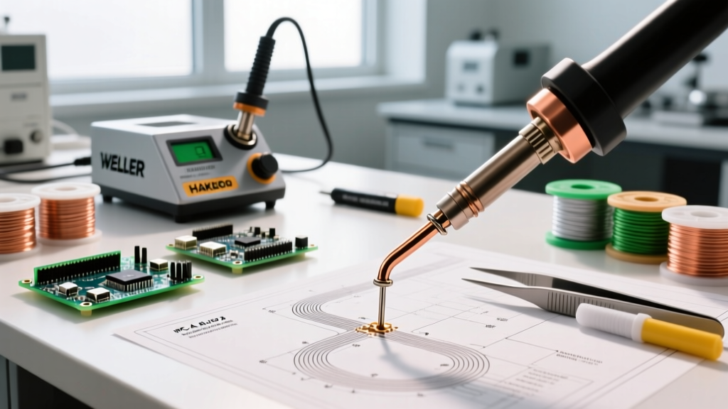
The market for electric soldering stations has evolved significantly. While traditional transformer-based analog stations still exist, modern digital and USB-C PD (Power Delivery) irons dominate the 2026 landscape. Below is a comparison of the top three stations for electrical wiring work.
| Model | Wattage | Temp Range | Thermal Recovery | 2026 Est. Price |
|---|---|---|---|---|
| Weller WE1010NA | 70W | 200°C - 450°C | Excellent (Active Sensor) | $135 - $145 |
| Hakko FX-888D | 65W | 200°C - 480°C | Good (Ceramic Heater) | $115 - $125 |
| Pinecil V2 (USB-C PD) | 65W (via PD) | 100°C - 450°C | Ultra-Fast (RISC-V PID) | $30 - $40 |
Expert Verdict: For heavy electrical wiring (AWG 14 and thicker), the Weller WE1010NA remains the benchmark due to its massive thermal mass and proprietary active tip sensor. However, for PCB work and lighter electric wires (AWG 18-24), the Pinecil V2 offers unparalleled portability and PID temperature control at a fraction of the cost, provided you pair it with a 65W GaN USB-C power brick.
Metallurgy: Choosing the Right Solder Alloy
The alloy you choose dictates your working temperature, joint strength, and long-term reliability. When soldering electric circuits, you generally choose between two primary alloys:
Sn60/Pb40 (Tin/Lead Eutectic)
Melting at a precise 183°C (361°F), eutectic solder transitions instantly from solid to liquid without a plastic (semi-solid) state. This is crucial for electric connections because any movement during the plastic phase causes microscopic fractures, leading to a disturbed joint. Kester 44 (with a rosin-core flux) remains the gold standard for DIY and commercial electrical repair.
SAC305 (Lead-Free)
Composed of 96.5% Tin, 3.0% Silver, and 0.5% Copper, SAC305 is the industry standard for RoHS-compliant manufacturing. It melts at a higher 217°C - 220°C. When soldering electric components with SAC305, you must increase your iron temperature to roughly 350°C to 380°C to ensure proper wetting. Be warned: lead-free solder requires more aggressive fluxes and accelerates tip oxidation, requiring you to clean and re-tin your tip frequently.
Pro Tip: Never mix leaded and lead-free solders on the same electric connection. Bismuth and lead contamination in a SAC305 joint creates a brittle intermetallic compound that will fracture under minor mechanical vibration.
Step-by-Step: The Western Union Splice
When soldering electric wires inline, mechanical strength must precede electrical conductivity. Solder is not glue; it is an electrical bridge. The Western Union (or Lineman's) splice provides the necessary tensile strength.
- Strip the Wires: Remove exactly 1.5 inches of insulation from both AWG 18-14 stranded wires. Do not nick the copper strands.
- Cross and Twist: Cross the wires at a 45-degree angle. Grip the ends with lineman's pliers and twist each side 3 to 4 times tightly.
- Apply Flux: Even if using rosin-core solder, apply a thin layer of liquid Kester 186 RMA (Rosin Mildly Activated) flux to the twisted splice. This prevents oxidation during the extended heating time required for thick wire.
- Heat the Wire, Not the Solder: Press the flat side of your chisel tip against the bottom of the splice. Wait 2-3 seconds for the copper to reach 183°C.
- Feed the Solder: Touch 0.031-inch rosin-core solder to the top of the wire, opposite the iron. Capillary action will draw the molten solder through the twist. Stop when a smooth fillet forms between all strands.
Common Failure Modes in Electric Solder Joints
Identifying a bad joint is just as important as making a good one. The NASA Electronic Parts and Packaging (NEPP) Program outlines several critical failure modes in electrical wiring:
- Cold Joints: Characterized by a dull, grainy, or lumpy appearance. Caused by insufficient heat or moving the wire before the solder solidifies. These joints have high electrical resistance and generate excess heat under load.
- Solder Wicking: When solder travels too far under the wire insulation. This creates a rigid point right at the flex zone of the wire. Over time, vibration will snap the copper strands exactly at the edge of the insulation.
- Flux Inclusions (Voids): Trapped flux bubbles inside the joint. Often caused by applying solder too quickly before the flux has fully boiled off and activated. These voids reduce the cross-sectional area of the conductor.
- Thermal Damage: Melted or scorched wire insulation. This occurs when using an undersized iron that requires prolonged contact (10+ seconds) to heat the wire, eventually melting the PVC or Teflon jacket.
Soldering vs. Crimping: When to Use Which?
A frequent debate in electrical engineering is whether to solder or crimp. The answer depends entirely on the environment.
Choose Soldering When: You are working on static electronics, PCBs, avionics, or environments where moisture resistance is paramount (solder seals out oxygen). Soldering is also superior for high-frequency RF connections where skin effect requires a continuous, smooth metallic path.
Choose Crimping When: You are wiring automotive harnesses, heavy machinery, or high-vibration environments. A properly executed crimp (using a ratcheting die and matching terminal) creates a cold-weld that is actually more resistant to mechanical fatigue and vibration than a soldered joint, which can work-harden and crack over time.
Frequently Asked Questions
Can I use plumbing solder for electric wires?
No. Plumbing solder (often 50/50 Tin/Lead or lead-free with acid core) uses an aggressive acid flux designed to eat through copper oxide on pipes. If used on electric wires, the acid flux will corrode the copper strands over time, leading to catastrophic failure and potential short circuits. Always use rosin-core flux for electronics.
Why does my solder ball up and refuse to stick to the wire?
This is a wetting failure, usually caused by oxidation on the copper wire or a dirty iron tip. Clean the wire with isopropyl alcohol and fine grit sandpaper, apply fresh rosin flux, and ensure your tip is properly tinned. If the tip is black and oxidized, use a brass wire sponge and tip tinner compound to restore it.
What wattage is best for soldering electric guitar pots?
Guitar potentiometers have large metal casings that act as massive heat sinks. A standard 30W craft iron will fail. Use a temperature-controlled station set to 400°C (750°F) with a minimum of 60W-70W, and use a large bevel or chisel tip to maximize surface area contact. Limit contact time to 5 seconds to prevent melting the internal plastic wiper.