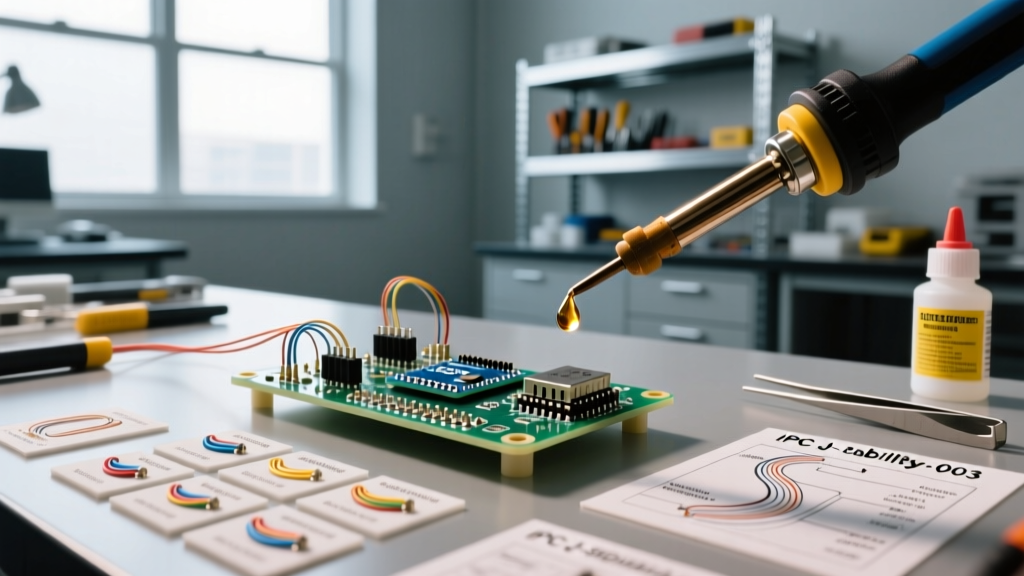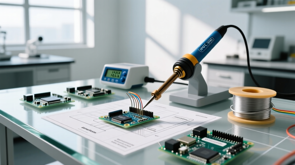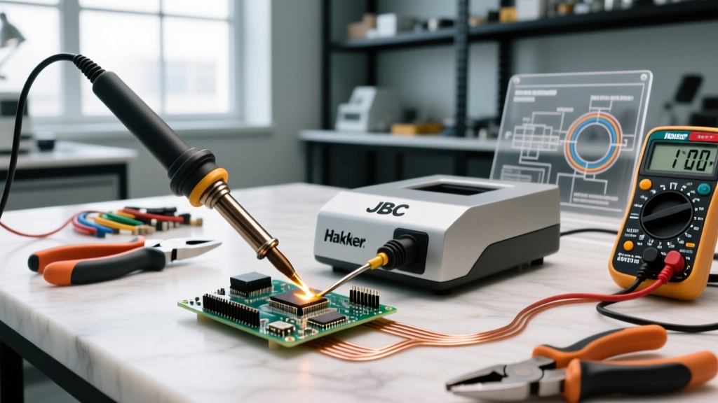

The Evolution of Soldering Tech: Beyond Basic Resistive Heating
As we navigate the electronics manufacturing and DIY landscape in 2026, modern soldering tech has moved far beyond simple resistive heating elements and analog dials. Today's professional workbenches are dominated by IoT-enabled smart stations, high-frequency induction heating, and localized micro-climate nitrogen systems. However, with advanced microprocessors and proprietary tool-handshake protocols comes a new layer of complexity. When a $600 smart station throws a cryptic error code or fails to recover thermally on a heavy ground plane, standard troubleshooting guides fall short.
This comprehensive FAQ and troubleshooting guide dives deep into the architecture of modern soldering tech, providing actionable, hardware-level solutions for the most common faults encountered with industry-leading platforms from JBC, Hakko, and Weller.
Core Soldering Tech Troubleshooting Matrix
Before replacing expensive handpieces or control bases, consult this fault matrix. Many modern errors stem from communication breakdowns between the base station's microcontroller and the tip's embedded sensors.
| Equipment Model | Fault Code / Symptom | Root Cause Analysis | Hardware-Level Fix |
|---|---|---|---|
| JBC CD-2BQE | E04 Error on Display | Cartridge not detected; internal thermocouple break or oxidized 4-pin connector. | Clean handpiece connector with 99% IPA and fiberglass pen. Inspect C245 cartridge pins for pitting; replace if arcing has damaged the contacts. |
| Hakko FX-951 | Red LED Flashing / Beeping | Sensor failure; broken ceramic heating element wire or improper T12 tip seating. | Verify T12 tip seating depth (must be exactly 18mm). If seated correctly, the internal composite sensor wire is fractured; replace the handpiece assembly. |
| Weller WX2021 | "Tool Not Recognized" | EEPROM handshake failure between the RT3 tip and the base station microcontroller. | Hard reboot the base station. Clean RT3 micro-contacts. If persistent, update WX2021 firmware via USB-C to v2.1+ to resolve known I2C bus timeouts. |
Advanced FAQ: Resolving Smart Station Faults
Why does my induction-based station show thermal lag on heavy ground planes?
Many users upgrading to high-frequency induction soldering tech (like the JBC CD-2BQE or Quick 861DW) assume that a 130W rating guarantees instant thermal recovery. However, thermal lag on multi-layer PCBs with heavy copper pours (e.g., 2oz+ copper on a 4-layer board) is often a tip geometry issue, not a station wattage issue. If you are using a 0.5mm micro-pencil tip (like the JBC C115-112) on a massive ground plane, the physical thermal mass of the tip is insufficient to transfer the station's available wattage into the joint. Solution: Switch to a high-thermal-mass bevel or chisel tip (e.g., JBC C245-945 or Hakko T12-D24) to increase the surface area contact. The station can only deliver energy as fast as the tip's physical mass can transfer it.
How do I fix cold joints when using lead-free SAC305 solder with smart stations?
Lead-free SAC305 (Sn96.5/Ag3.0/Cu0.5) requires a minimum liquidus temperature of 217°C, but practical working temperatures demand 350°C–380°C at the joint interface. According to the IPC J-STD-001 standards for soldered electrical assemblies, insufficient wetting in lead-free applications is rarely a flux issue; it is a thermal deficit. If your smart station drops below 320°C during the joint formation, the flux activates and burns off before the solder alloys, resulting in a dull, grainy cold joint. Solution: Enable the "Boost" or "Heavy Load" thermal profile on your Weller or JBC station, which pre-empts thermal droop by overdriving the heating element by 15% the moment the tip's thermocouple detects a 5°C drop.
Why is my modern soldering tip turning black and rejecting solder?
Oxidation is the enemy of modern soldering tech. Unlike older leaded solders that contained highly active rosin fluxes capable of cleaning mild oxidation, modern no-clean and lead-free fluxes are chemically milder to meet environmental and outgassing regulations. If your tip turns black, it has formed a layer of iron oxide that solder cannot wet. This is usually caused by excessive idle temperatures or using a wet cellulose sponge. Water causes rapid thermal shock, creating micro-fractures in the tip's iron plating, allowing the internal copper core to oxidize and swell, destroying the tip from the inside out.
Decoding Thermal Recovery Metrics in 2026
When evaluating modern soldering tech, manufacturers often advertise "2-second thermal recovery." It is critical to understand what this metric actually means. Recovery time is measured from the moment the tip contacts a standardized thermal sink (usually a specific mass of brass) until the embedded thermocouple reads the set temperature again.
- JBC Cartridge Tech: The thermocouple is integrated directly into the tip cartridge, millimeters from the working face. This provides near-instantaneous feedback, resulting in true < 2-second recovery times.
- Hakko T12 Composite Tech: The sensor is embedded in the ceramic heater, and the hollow tip slides over it. The air gap and mechanical tolerances between the heater and the tip introduce a slight thermal latency, typically resulting in 4 to 6-second recovery times.
- Weller RT3 Active Tech: Uses a similar integrated approach to JBC but relies on a proprietary micro-EEPROM handshake, offering < 3-second recovery with extreme precision (±1°C variance).
Is Nitrogen-Assisted Soldering Tech Worth the Investment?
Nitrogen (N2) soldering tech surrounds the work area with an inert gas blanket, displacing oxygen and preventing oxidation. But with N2 generators costing between $600 and $1,200, and specialized N2 handpieces adding another $250 to your bill, is the ROI justifiable for non-industrial users?
| Factor | Standard Air Environment | Nitrogen-Assisted Environment |
|---|---|---|
| Tip Lifespan | 3–6 months (heavy use) | 12–18 months (heavy use) |
| Flux Consumption | High (flux burns off to fight O2) | Low (flux preserved for wetting) |
| Maximum Safe Temp | 380°C (rapid degradation above) | 420°C (safe for heavy RF shields) |
| Joint Aesthetics | Duller on lead-free SAC305 | Bright, shiny, mirror-like finish |
Verdict: If you primarily work on micro-BGA rework, 0201 SMD components, or high-reliability aerospace/automotive boards where IPC Class 3 standards apply, N2 soldering tech is mandatory. For general through-hole and standard SMD prototyping, the ROI is difficult to justify.
Preventative Maintenance Protocol for Modern Equipment
To maximize the lifespan of your investment in advanced soldering tech, adhere to this strict shutdown protocol. The NASA Workmanship Training standards heavily emphasize proper tip tinning to prevent atmospheric corrosion during storage.
- Never use a wet sponge. Replace all cellulose sponges with a dry brass wire cleaner (e.g., Hakko 599B or JBC CLS-A). Brass is softer than the iron plating and will not score the tip.
- The 60-Second Shutdown Rule. When powering down your station, do not simply flip the switch. Lower the temperature to 250°C, roll the tip in a high-rosin, water-soluble flux (like Kester 186), and apply a thick layer of 63/37 leaded solder wire.
- Cap the Handpiece. Modern stations like the Weller WX series come with silicone protective caps. Always use them. Leaving a hot tip exposed to ambient humidity accelerates iron oxidation exponentially.
- Calibrate Bi-Annually. Use a high-precision tip thermometer (e.g., Hakko FG-100B) to verify the station's digital readout against the actual physical tip temperature. Drift of more than 5°C requires entering the calibration offset menu.
Expert Insight: "The most common failure mode I see in modern soldering tech isn't the electronics—it's the mechanical abuse of the handpiece. Dropping a JBC or Weller handpiece on a hard floor can misalign the internal ceramic heater or fracture the micro-thermocouple wires, leading to phantom E04 or sensor errors that cannot be fixed via software. Always use a magnetic handpiece holder with a silicone dampener."
Final Thoughts on Soldering Tech Diagnostics
Troubleshooting modern soldering tech requires shifting your mindset from simple electrical continuity to understanding thermal dynamics, micro-controller handshakes, and metallurgical chemistry. By utilizing the fault matrices and maintenance protocols outlined above, you can minimize downtime, protect your expensive cartridges, and ensure every joint meets rigorous 2026 manufacturing standards.