
Choosing the right solder wire is only half the battle; understanding how different solders behave under thermal stress is what separates a novice from a master technician. Whether you are reworking a dense multilayer PCB or assembling high-reliability aerospace connectors, the metallurgical properties of your chosen alloy dictate your success. In 2026, the electronics industry relies on a diverse spectrum of solders—from classic eutectic tin-lead to advanced low-temperature bismuth blends designed for thermal-sensitive components. This guide dives deep into the most frequently asked questions and troubleshooting scenarios regarding electronic solders, flux chemistries, and joint failure analysis.
The Metallurgy of Solders: Quick Reference Matrix
Before troubleshooting a failed joint, you must understand the thermal profile of the alloy you are using. Different solders possess distinct melting points, plastic ranges, and tensile strengths. According to the IPC standards for soldering materials, selecting an alloy mismatched to your component's thermal mass is the root cause of 60% of field failures.
| Alloy Designation | Composition | Melting Point (°C) | Plastic Range | Primary Application |
|---|---|---|---|---|
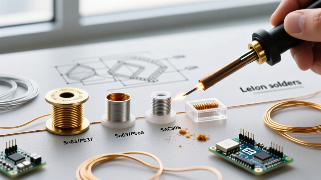
| Sn63Pb37 | 63% Tin / 37% Lead | 183°C | None (Eutectic) | General purpose, hand soldering, rework |
| SAC305 | 96.5% Sn / 3.0% Ag / 0.5% Cu | 217°C - 220°C | None (Near-Eutectic) | RoHS compliant SMT, wave, and hand soldering |
| Sn42Bi58 | 42% Tin / 58% Bismuth | 138°C | None (Eutectic) | Thermal-sensitive components, step-soldering |
| Sn96.5Ag3.5 | 96.5% Tin / 3.5% Silver | 221°C | None (Eutectic) | High-reliability, high-vibration environments |
FAQ: Choosing the Right Solder Alloy and Flux
Q: Does the physical diameter of the solder wire matter for PCB work?
Absolutely. The diameter of your solder wire controls the volume of flux delivered to the joint and the rate at which the alloy melts. For standard through-hole components and 0805 surface-mount devices, a 0.031" (0.8mm) diameter is optimal. However, when working with 0402 or 0201 micro-components, using a thick wire will flood the pad and cause bridging. For micro-soldering, technicians must drop down to 0.015" (0.38mm) or even 0.010" (0.25mm) wire. Thinner solders also contain a higher flux-to-alloy ratio by volume, which aids in wetting microscopic pads where oxidation is a primary concern.
Q: What is the practical difference between R, RMA, RA, and No-Clean flux cores?
The flux core inside your solder wire is just as critical as the metal itself. The AIM Solder technical resources outline these core chemistries clearly:
- R (Rosin): Pure, unactivated rosin. Extremely safe but lacks the chemical aggression to cut through heavy oxidation. Best for pristine, new components.
- RMA (Rosin Mildly Activated): The industry workhorse. Contains mild activators that clean light oxidation without leaving highly corrosive residues. Requires cleaning in high-reliability applications.
- RA (Rosin Activated): Highly aggressive. Used for heavily oxidized boards or tarnished wires. Must be thoroughly cleaned with isopropyl alcohol or specialized saponifiers post-soldering to prevent dendritic growth and electrical leakage.
- No-Clean (NC): Formulated with synthetic resins that leave a benign, non-conductive, and non-corrosive residue. Ideal for modern high-density boards where washing is impossible. However, NC fluxes often require slightly higher tip temperatures to activate fully.
Q: Why do modern lead-free solders feel "sluggish" compared to tin-lead?
Lead acts as a surfactant, drastically reducing the surface tension of the molten alloy. When the industry shifted to lead-free solders like SAC305, the removal of lead increased the alloy's surface tension, resulting in poorer wetting and a "sluggish" flow. To compensate, you must increase your soldering iron tip temperature by 30°C to 40°C (typically running at 340°C - 360°C) and use a high-activity No-Clean or water-soluble flux core to break down oxides faster.
Troubleshooting Guide: Diagnosing Solder Joint Failures
When a solder joint fails visual inspection or functional testing, the physical appearance of the joint provides a forensic roadmap to the root cause. Here is how to diagnose the most common anomalies.
1. The "Grainy" or Disturbed Joint
Symptom: The joint appears dull, frosted, or cracked with a distinct granular texture under magnification.
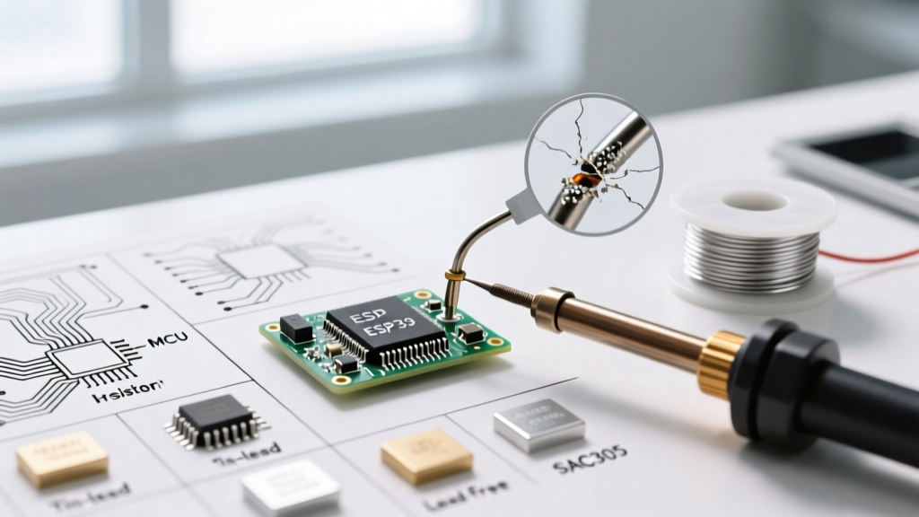
The Physics: This occurs when the joint is physically disturbed while the alloy is in its "plastic state" (the phase between liquidus and solidus temperatures). While eutectic solders like Sn63Pb37 transition instantly from liquid to solid, non-eutectic solders like Sn60Pb40 have a 5°C plastic range. If the component lead shifts during this 5-degree window, the crystalline structure fractures.
Solution: Switch to a true eutectic alloy (Sn63Pb37) to eliminate the plastic range entirely. Alternatively, use a fixture or third-hand tool to hold the component absolutely rigid until the joint cools below 150°C.
2. Solder Balling and Flux Splatter
Symptom: Tiny spheres of solder scatter across the PCB, and the flux spits violently when the iron touches the wire.
The Physics: This is almost always a moisture or thermal shock issue. If the flux core contains absorbed ambient humidity, the water instantly flashes to steam upon contact with a 350°C iron tip, causing micro-explosions that eject molten solder. It can also occur if the iron tip temperature is set excessively high, causing the rosin to boil rather than melt and flow.
Solution: Store your solders in a dry cabinet or sealed bag with desiccant. According to Kester technical guidelines, solder wire should be kept in environments with less than 10% relative humidity. Additionally, lower your iron temperature to the minimum required to achieve wetting within 2 to 3 seconds.
3. Dewetting and Non-Wetting
Symptom: Non-wetting occurs when the solder refuses to adhere to the pad, forming a high contact angle (>90°) and pulling away like water on a waxed car. Dewetting occurs when the solder initially flows but then retracts, leaving a thin, irregular film and exposing the base metal.
The Physics: Non-wetting is caused by a severe barrier to the intermetallic compound (IMC) layer formation, usually due to heavy oxidation, contamination (like silicone conformal coating), or an insufficiently active flux. Dewetting happens when the base metal dissolves into the solder bath (leaching), or when the flux is completely exhausted before the joint reaches thermal equilibrium.
Solution: For non-wetting, manually clean the pad with a fiberglass scratch pen and apply external liquid RMA flux before attempting to solder. For dewetting, reduce your dwell time. If you hold a 380°C iron on a small pad for more than 4 seconds, the copper pad may detach from the FR4 substrate or the surface finish (like ENIG) will dissolve entirely into the molten pool.
4. Cold Joints (The Misunderstood Failure)
Symptom: A lumpy, asymmetrical joint with poor fillet formation and a visibly distinct boundary between the solder and the component lead.
The Physics: A cold joint is rarely caused by the iron being set to a low temperature. It is almost always caused by insufficient thermal transfer. If you are soldering a large ground plane with a micro-pencil tip, the tip's thermal mass is instantly depleted by the copper plane. The solder wire melts against the iron, but the PCB pad never reaches the alloy's liquidus temperature, resulting in a superficial, mechanically weak bond.
Solution: Match your tip geometry to the thermal mass of the joint. Use a chisel or bevel tip to maximize surface area contact. Apply the iron to the pad and lead simultaneously, feed the solder into the joint (not onto the iron tip), and wait for the flux to flash and the solder to wick via capillary action.
Storage and Shelf Life: Why Your Solder Wire Degrades
Expert Insight: Solder wire does not last forever. The organic flux core is susceptible to oxidation and solvent evaporation. Over time, the flux dries out, losing its ability to lower surface tension and dissolve metal oxides. If your solder wire feels brittle or leaves a hard, crusty residue that refuses to flow, the flux core has expired.
To maintain peak performance, leaded solder wires with rosin-based fluxes generally have a shelf life of 3 to 5 years when stored correctly. Lead-free alloys and water-soluble flux cores are more volatile and typically carry a strict 1 to 2-year shelf life. Always write the date of opening on the spool, and store your solders in a climate-controlled environment away from direct UV light, which degrades the synthetic resins in No-Clean formulations.
Mastering the nuances of different solders requires moving beyond the basic "melt and stick" mentality. By understanding the metallurgical phase changes, matching flux chemistry to your specific oxidation levels, and diagnosing joint failures through a scientific lens, you will drastically improve the reliability and longevity of your electronic assemblies.