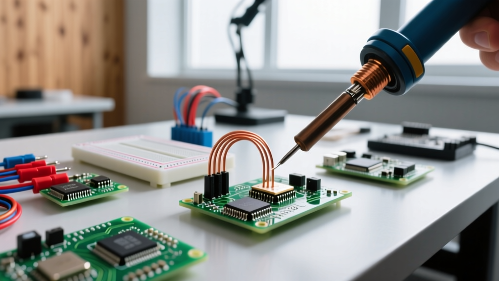

The Great Debate: Hardwiring vs. Socketing Overcurrent Protection
When designing custom wire harnesses, building battery packs, or repairing legacy electronics, the practice of soldering fuses directly to wire pigtails remains a polarizing topic among engineers and DIYers. On one side, direct soldering offers a permanent, low-resistance, and space-saving connection. On the other, inline fuse holders and PCB clips provide easy replacement and compliance with accessibility codes. As of 2026, with the rise of high-density lithium-ion battery management systems (BMS) and compact IoT devices, choosing the right integration method is more critical than ever.
This comprehensive method comparison breaks down the thermal risks, mechanical reliability, and code compliance of soldering fuses directly versus using dedicated holders, giving you the exact data needed to make an informed design choice.
Method 1: Direct Soldering (The Pigtail Approach)
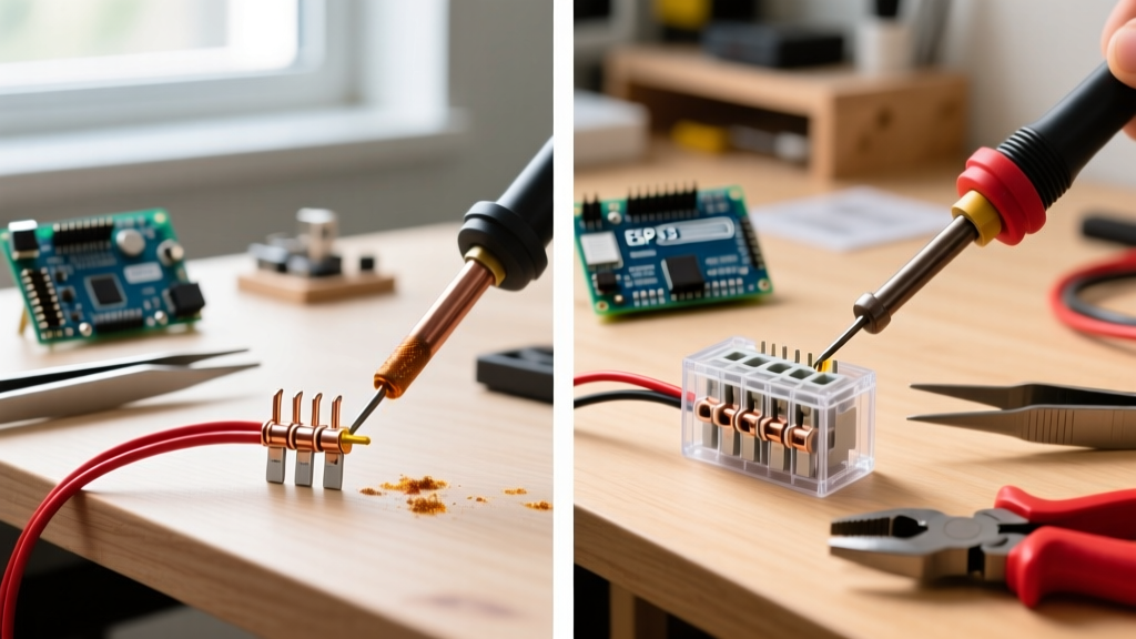
Direct soldering involves attaching a wire lead directly to the metal end cap of a cartridge fuse (such as a 5x20mm or 6.3x32mm glass/ceramic tube) or surface-mounting an SMD fuse directly to a PCB pad. In custom wire harnesses, this is often done to create a "sealed" inline fuse that is subsequently encased in heat shrink or epoxy.
Where Direct Soldering Excels
- Space Constraints: In ultra-compact IoT devices or drone ESCs, there is simply no physical room for a bulky inline holder.
- Vibration Resistance: Soldered joints, when properly strain-relieved, eliminate the micro-arcing and contact resistance issues that plague loose-fitting fuse holders in high-vibration environments.
- Cost Efficiency: Bypassing the holder saves between $0.80 and $2.50 per unit in high-volume production.
The Fatal Flaw: Thermal Degradation
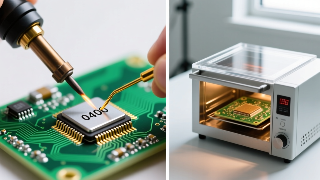
The primary argument against soldering fuses directly is heat transfer. The internal fusible element in a standard fast-acting glass fuse (like the Littelfuse 218 Series) is often made of zinc, copper, or tin alloys with relatively low melting points. If a 60W soldering iron set to 380°C (716°F) is applied to the end cap for more than 3 to 4 seconds, the heat conducts through the cap and alters the metallurgical properties of the internal element. This can cause the fuse to blow prematurely at currents well below its rated amperage, or worse, fail to blow during a genuine short circuit.
Method 2: Inline Fuse Holders & PCB Clips
Inline fuse holders (such as the Keystone 3544 or Littelfuse LEC series) and PCB-mount clips (like the Keystone 354) utilize mechanical spring tension or crimped terminals to secure the fuse. This is the industry standard for user-serviceable electronics.
Advantages of Mechanical Holders
- Zero Thermal Damage: The fuse is inserted cold, completely eliminating the risk of heat-induced element degradation.
- Serviceability: Blown fuses can be swapped in seconds without requiring a soldering iron, desoldering wick, or replacement heat shrink.
- Code Compliance: Meets the "readily accessible" requirements for overcurrent protection in many commercial and residential applications.
Drawbacks to Consider
Mechanical holders introduce contact resistance. Over time, oxidation on the brass or nickel-plated contacts can increase resistance, leading to localized heating (the "hot holder" syndrome). In high-current DC applications (e.g., 12V/24V automotive or solar), a poor-quality holder can melt before the fuse ever blows.
⚠️ Thermal Shock Warning for Glass FusesGlass fuses are highly susceptible to thermal shock. Differential expansion between the metal end cap and the glass tube during soldering can cause micro-fractures. These fractures compromise the hermetic seal, allowing oxygen to enter. When the fuse eventually blows, the presence of oxygen can cause the internal element to oxidize violently, potentially shattering the glass tube inside your enclosure. Always use ceramic body fuses (e.g., 5x20mm ceramic HRC) if direct soldering is absolutely mandatory.
Comparison Matrix: Soldering Fuses vs. Using Holders
| Feature | Direct Soldering (Pigtails) | Inline / PCB Holders |
|---|---|---|
| Material Cost (per unit) | $0.15 - $0.30 (Wire + Solder) | $0.80 - $2.50 (Holder + Crimp) |
| Assembly Time | 45 - 90 seconds (Requires heat sinking) | 10 - 20 seconds (Crimp or Snap-in) |
| Contact Resistance | Extremely Low (< 0.005 Ω) | Moderate (0.015 Ω - 0.050 Ω) |
| Vibration Tolerance | Excellent (If strain-relieved) | Poor to Fair (Prone to backing out) |
| Field Replaceability | Impossible (Requires cutting/splicing) | Excellent (User-serviceable) |
| NEC Article 240 Compliance | Fails (Not readily accessible) | Passes (If externally accessible) |
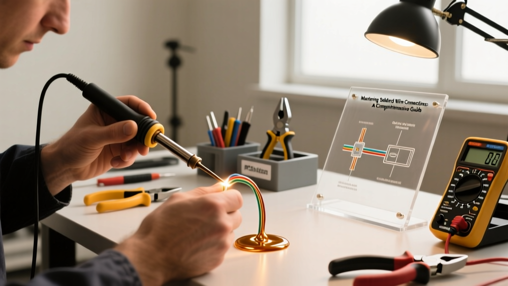
Step-by-Step: How to Safely Solder a Pigtail to a Cartridge Fuse
If your design dictates that you must solder directly to a fuse (e.g., potting a BMS in epoxy), you must follow strict thermal management protocols to meet IPC-A-610 acceptability standards and prevent component damage.
Required Tools and Materials
- Temperature-controlled soldering station (e.g., Hakko FX-888D or Pinecil V2) set to exactly 350°C (662°F) for 63/37 Sn/Pb solder, or 380°C (716°F) for SAC305 lead-free.
- Aluminum hemostats or copper heat-sink clips.
- High-quality rosin-core flux (e.g., Amtech NC-559).
- 18 AWG or 20 AWG stranded silicone wire.
- Adhesive-lined (dual-wall) heat shrink tubing.
The Procedure
- Prep the Wire: Strip 1/4 inch of insulation. Twist the strands tightly and pre-tin the wire with a minimal amount of solder. The tinned section should not exceed 1/8 inch.
- Apply Heat Sinking: Clamp the aluminum hemostats firmly onto the metal end cap of the fuse, leaving only a 2mm exposed area at the very tip for soldering. The aluminum will absorb the bulk of the thermal energy, protecting the internal element.
- Flux the Cap: Apply a small drop of liquid or gel flux to the exposed tip of the fuse cap. Do not use acid-core plumbing flux, as it will corrode the cap over time.
- The 3-Second Rule: Touch the iron tip to the fuse cap, then immediately introduce the pre-tinned wire. The solder should flow and wet the cap within 2 to 3 seconds. Remove the iron immediately. If it does not flow in 3 seconds, stop, let the component cool for 30 seconds, add more flux, and try again.
- Strain Relief: Slide a piece of dual-wall heat shrink over the joint. Ensure the shrink extends at least 1/2 inch over the wire insulation and 1/8 inch onto the glass/ceramic body of the fuse. Apply heat until the inner adhesive oozes slightly from the ends, creating a waterproof, mechanical strain relief.
"In high-reliability aerospace and medical applications, direct soldering to glass fuses is almost universally banned. Engineers instead specify ceramic HRC (High Rupturing Capacity) fuses with axial pigtails that are factory-welded, or they utilize specialized PCB-mount fuse clips that withstand high-G shock testing."
— Senior Reliability Engineer, Avionics Power Systems
Automotive & High-Current DC: Why You Never Solder Blade Fuses
When moving from low-current electronics (under 10A) to automotive or solar DC applications (15A to 100A+), the rules change entirely. You should never attempt to solder wires directly to the blades of an ATC, ATO, or MAXI automotive fuse. The high thermal mass of the blade requires prolonged heat, which will instantly melt the internal zinc element and ruin the fuse.
Furthermore, solder is mechanically weak under the hood of a vehicle. Engine bay temperatures can exceed 125°C (257°F), which approaches the creep threshold of standard tin-lead solders. Vibration will cause the solder joint to fatigue and crack, leading to high-resistance arcing and potential vehicle fires.
The Correct Method: Crimping
For inline automotive fuse holders, always use crimp connections. Utilizing a ratcheting crimp tool (such as the TE Connectivity AMP CERTI-CRIMP) with nylon-insulated, fully-insulated female disconnect terminals ensures a cold, gas-tight, and vibration-proof mechanical bond. This method conforms to automotive wiring standards (like SAE J1128) and ensures the fuse remains the single, deliberate weak point in the circuit.
Code Compliance: NEC Article 240 and Accessibility
For DIYers wiring custom projects into residential or commercial structures, understanding the National Electrical Code (NEC) is mandatory. NEC Article 240 dictates the rules for overcurrent protection devices.
Specifically, the NEC requires that overcurrent devices be readily accessible. If you are building a custom hardwired appliance or a smart home relay panel and you choose to solder a fuse directly to the internal wiring and seal it inside a junction box, you are likely creating a code violation. An inspector will require a fuse holder that can be accessed without dismantling the enclosure or cutting wires. Direct soldering of fuses is generally restricted to internal, component-level protection on PCBs (like a 5x20mm fuse inside a sealed power supply brick), where the primary branch-circuit protection is handled by an accessible breaker in the main panel.
Final Verdict: Which Method Should You Choose?
There is no universal "best" method for integrating fuses; the correct choice depends entirely on the environment and serviceability requirements of your project.
- Choose Direct Soldering If: You are building sealed, potted, or ultra-compact internal electronics (like a drone ESC or internal battery BMS) where vibration resistance and minimal footprint outweigh the need for field serviceability. Always use ceramic fuses and strict heat-sinking protocols.
- Choose Inline Holders If: You are building user-serviceable equipment, automotive wire harnesses, solar combiner boxes, or any project that interfaces with building wiring. The slight increase in cost and contact resistance is vastly outweighed by safety, code compliance, and ease of maintenance.
By understanding the thermal limitations of fusible alloys and the mechanical realities of solder joints, you can design overcurrent protection that is both safe and reliable for years to come.