
Selective Soldering Equipment: Buyer FAQ & Troubleshooting Guide
Selective soldering bridges the critical gap between manual hand soldering and traditional wave soldering, offering pinpoint accuracy for complex, mixed-technology PCBs. However, capital expenditure for selective soldering equipment is significant, and process defects can severely impact yield rates in high-mix production environments. This comprehensive FAQ and troubleshooting guide addresses the most vital buyer considerations and process engineering challenges faced by electronics manufacturers today.
Part 1: Equipment Evaluation & Buyer FAQ
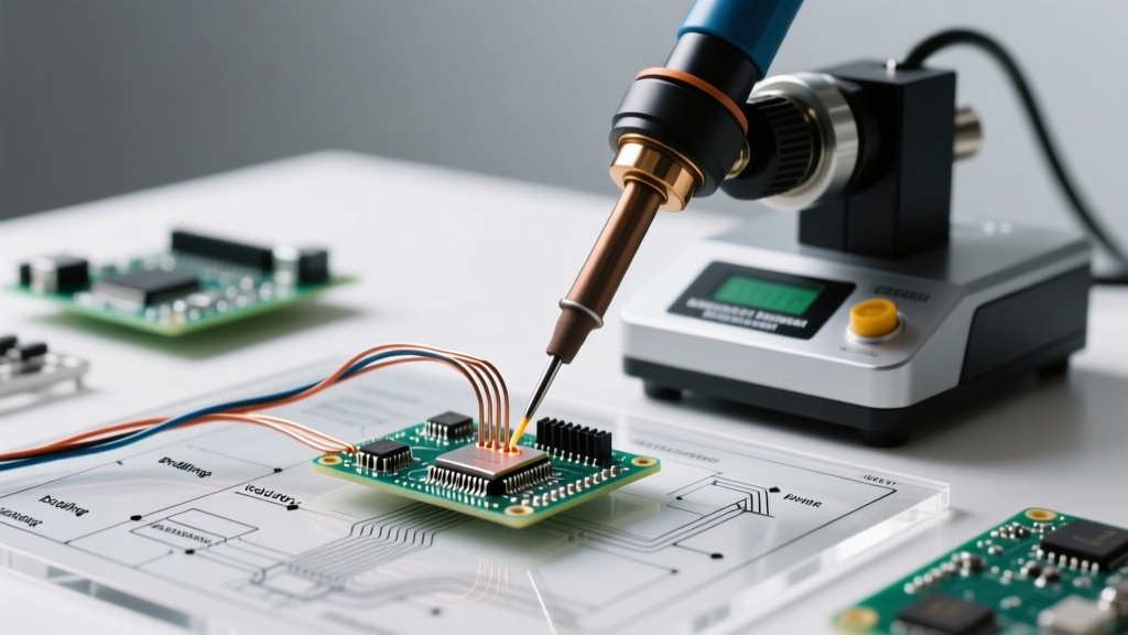
Before troubleshooting process defects, you must ensure your equipment baseline is correctly specified for your production volume and PCB complexity. Modern selective soldering systems utilize multi-axis gantries, drop-jet fluxers, and localized nitrogen inerting to achieve IPC Class 3 reliability.
Machine Tier Comparison Matrix
| Equipment Tier | Typical Models (e.g., ERSA, Pillarhouse) | Estimated Capital Cost | Best Application | Key Specifications |
|---|---|---|---|---|
| Batch / Offline | Pillarhouse Jade MKII, ERSA VERSAFLOW 1 | $45,000 - $85,000 | Low-volume, high-mix, prototyping | Single solder pot, manual loading, basic flux spraying |
| Inline Entry-Level | ERSA VERSAFLOW 3/35, Kurtz Ersa | $110,000 - $160,000 | Mid-volume SMT/THT mixed lines | Drop-jet fluxer, single preheat zone, single solder module |
| High-End Multi-Station | ERSA VERSAFLOW 4/55, Pillarhouse Orion | $220,000 - $350,000+ | High-volume automotive, aerospace, medical | Dual solder pots, multi-zone IR preheat, localized N2 inerting, auto-nozzle changers |
What Nitrogen Purity is Required?
For optimal wetting and dross reduction, selective soldering equipment requires nitrogen purity of 99.99% (10 ppm O2 residual) at the nozzle tip. According to process engineering data from ERSA's selective soldering division, localized nitrogen inerting reduces dross generation by up to 80% compared to ambient air soldering, while significantly improving hole-fill capabilities on thick, multi-layer boards with high thermal mass ground planes.
Part 2: Troubleshooting Common Defect Modes
Even with premium equipment, process drift occurs. Below is an expert troubleshooting matrix for the most frequent selective soldering defects, aligned with the defect classifications found in IPC J-STD-001 and IPC-A-610 standards.
1. Solder Bridging (Shorts)
Bridging occurs when solder connects adjacent pads or leads, typically on fine-pitch connectors (e.g., 0.050" pitch).
- Root Cause: Improper drag vector, excessive dwell time, or insufficient flux activation.
- Corrective Action: Optimize the lift-off angle. The nozzle should drag parallel to the row of pins, then execute a 45-degree downward and outward lift-off at a speed of 2.0 to 3.0 mm/s. Ensure top-side preheat reaches 110°C - 130°C to fully activate the VOC-free flux before contact.
2. Icicles and Solder Peaks
Icicles are sharp, elongated protrusions of solder extending from the joint, violating IPC Class 3 clearance requirements.
- Root Cause: Solder bath temperature too low, Z-axis withdrawal speed too fast, or oxidized nozzle coating.
- Corrective Action: Increase the SAC305 solder pot temperature by 5°C (target range: 265°C - 275°C). Slow the Z-axis withdrawal speed to <1.5 mm/s to allow surface tension to break cleanly. Inspect the nozzle's wettable coating; if degraded, replace or re-condition the nozzle.
3. Non-Wetting and Dewetting
Non-wetting leaves the base metal exposed, while dewetting shows solder pulling back from the pad edges, leaving a thick, irregular fillet.
- Root Cause: Heavy oxidation on component leads, contaminated PCB pads, or inadequate thermal profiling.
- Corrective Action: Verify flux deposition volume using thermal paper or a flux-check station. For water-based fluxes, ensure the drop-jet pressure is maintained between 2.0 and 3.0 bar. If thermal mass is absorbing too much heat, increase the localized dwell time over the joint by 0.5 to 1.0 seconds before initiating contact.
Expert Insight: Never attempt to fix non-wetting by simply cranking up the solder pot temperature beyond 285°C. Excessive heat degrades the flux's activators prematurely and accelerates copper dissolution from the PCB pads, leading to catastrophic pad lifting on FR-4 substrates.
Part 3: Maintenance & Calibration FAQ
How often should drop-jet fluxers be cleaned?
Drop-jet fluxers are highly precise but susceptible to clogging from dried flux residue. In a 24/7 production environment, the fluxer head must be purged with the manufacturer's recommended solvent (typically isopropanol or a specialized DI-water blend) every 8 hours. Additionally, the micro-mesh filter in the flux supply line should be replaced monthly to prevent particulate contamination that causes uneven droplet deposition.
What is the lifespan of a selective solder nozzle?
Nozzle lifespan depends heavily on the solder alloy and maintenance regimen. For standard SAC305 (Tin/Silver/Copper) alloys, a high-quality nozzle with a proprietary wettable coating (such as ERSA's VarioSelect nozzles) will typically last between 400,000 and 600,000 solder cycles. However, if you are using high-reliability alloys with higher silver content or corrosive fluxes, expect lifespan to drop to 200,000 cycles. Implement an automated nozzle cleaning cycle utilizing a brass wire brush or specialized cleaning station every 50 cycles to prevent dross buildup on the nozzle exterior.
How do I calibrate the preheat IR sensors?
Closed-loop IR preheat systems rely on pyrometers reading the PCB surface temperature. Over time, flux overspray can coat the pyrometer lens, resulting in falsely low temperature readings and excessive, damaging heat application. Clean the pyrometer lens weekly with optical-grade wipes. Perform a monthly calibration verification using a specialized PCB thermocouple profile board (e.g., K-type thermocouples embedded in a dummy FR-4 board) to ensure the machine's IR feedback loop matches actual surface temperatures within ±3°C.
Summary: Achieving Process Stability
Mastering selective soldering equipment requires a holistic approach that balances mechanical precision, thermal dynamics, and chemical flux activation. By adhering to strict maintenance schedules, utilizing high-purity nitrogen, and applying the targeted troubleshooting steps outlined above, process engineers can consistently achieve zero-defect selective soldering yields compliant with the most stringent IPC Class 3 automotive and aerospace standards. Always document your machine's specific drag vectors, dwell times, and thermal profiles in a centralized SPC (Statistical Process Control) database to preemptively identify process drift before defects reach the inspection stage.