
The Comprehensive Guide to Glass Soldering in Modern Electronics
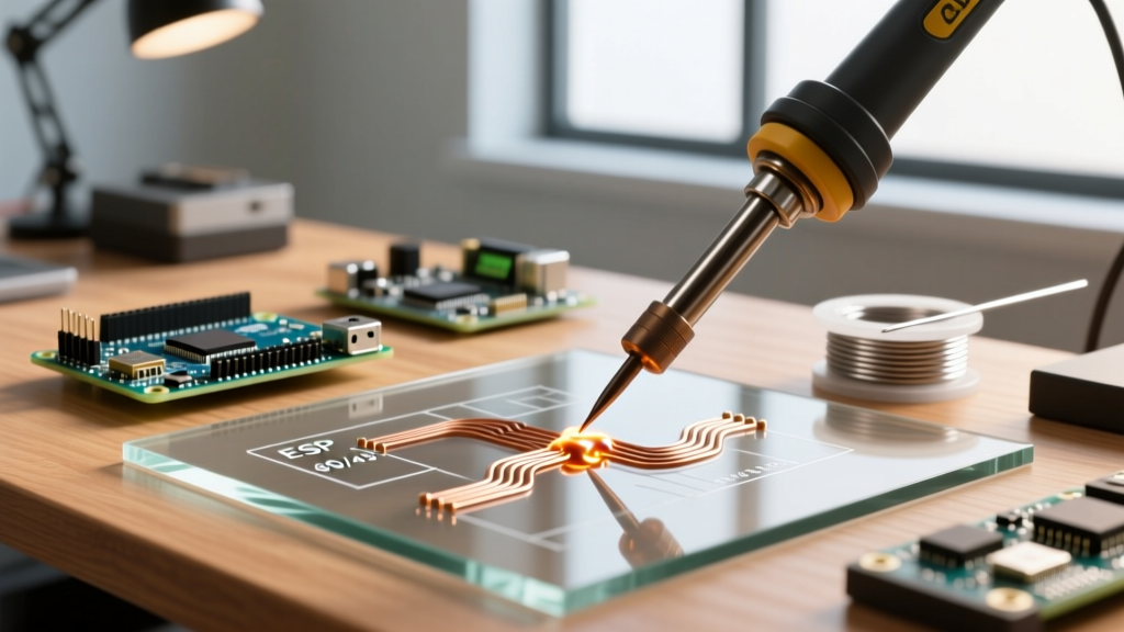
Soldering to glass—whether for integrating electronics into stained glass art, attaching busbars to thin-film solar cells, or wire-bonding to Indium Tin Oxide (ITO) displays—requires abandoning standard electronics assembly paradigms. Standard SAC305 or 60/40 tin-lead solders operate at temperatures that induce catastrophic thermal shock in glass substrates. Furthermore, bare glass lacks the metallic oxide layers that traditional rosin fluxes are designed to reduce, resulting in zero wetting and immediate joint failure.
As of 2026, the maker and professional electronics communities rely on two primary methodologies to overcome these physical barriers: low-temperature Indium-based alloys and fluxless ultrasonic soldering. This guide provides a deep-dive into the metallurgy, equipment, and step-by-step techniques required to successfully solder to glass without shattering your substrate or destroying delicate conductive coatings.
The Physics of Soldering to Glass: CTE and Wetting
To master glass soldering, you must first understand the two primary enemies of the process:
- Thermal Shock and CTE Mismatch: Glass is an amorphous solid with poor thermal conductivity and a very low Coefficient of Thermal Expansion (CTE). When a standard 350°C soldering iron touches a localized point on a glass pane, the rapid temperature gradient creates immense internal shear stress. The glass will micro-fracture or shatter entirely before the solder even melts.
- The Wetting Barrier: Solder wetting relies on a metallurgical bond between the molten alloy and the substrate's surface oxides. Because glass (silicon dioxide) does not form reducible metallic oxides, standard fluxes like RMA (Rosin Mildly Activated) are chemically useless on bare glass. The solder will simply ball up and roll off.
Choosing the Right Low-Temperature Solder Alloys
To prevent thermal shock, you must use alloys that melt well below the glass transition and stress-relief temperatures of your specific glass type (typically keeping the iron tip below 180°C). Indium-based alloys are the undisputed gold standard for electronics-grade glass soldering because Indium possesses a unique metallurgical property: it naturally wets to glass, ceramics, and quartz without the need for aggressive, corrosive fluxes.
| Alloy Designation | Composition | Melting Point | Approx. Cost (per oz) | Best Application |
|---|---|---|---|---|
| Indalloy 1E | 52% In, 48% Sn | 118°C (244°F) | $80 - $120 | ITO glass, delicate OLED sensors, solar cells |
| CerroLow 136 | 58% Bi, 42% Sn | 138°C (280°F) | $15 - $25 | Stained glass art integration, thermal fuses |
| Sn60/Pb40 (Control) | 60% Sn, 40% Pb | 183°C (361°F) | $2 - $4 | Standard PCBs (DO NOT USE ON GLASS) |
Expert Warning on Bismuth Alloys: While CerroLow 136 (Bismuth/Tin) is cheaper and melts at a safe 138°C, Bismuth alloys are notoriously brittle. They suffer from severe mechanical shear weakness and are prone to fatigue cracking under vibration. Use Bismuth only for static, decorative stained-glass electronics where the joint will never be physically stressed. For functional electronics, Indium is mandatory.
The Fluxless Revolution: Ultrasonic Glass Soldering
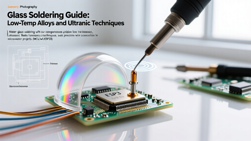
If you are soldering to bare glass (not ITO-coated) or aluminum, chemical fluxes often fail or leave corrosive residues. The modern solution is ultrasonic soldering. Ultrasonic soldering irons operate by vibrating the tip at high frequencies (typically 20kHz to 60kHz).
When the molten solder contacts the glass, the ultrasonic vibrations create microscopic cavitation bubbles in the liquid metal. As these bubbles collapse against the glass surface, they generate localized pressures exceeding 1,000 atmospheres. This acoustic scrubbing mechanically removes surface contaminants and breaks the molecular barrier, allowing the solder to bond directly to the bare glass substrate without any chemical flux.
Top Ultrasonic Systems for 2026
- MST Ultrasonic Soldering Iron (Model US-300): Priced around $1,800, this is the industry standard for lab-grade glass-to-metal seals. It features precise 60kHz frequency control and integrated solder feed.
- Sunbonder Handheld Ultrasonic Pen: A more accessible option for advanced makers, costing roughly $600-$900. Excellent for small-scale stained glass repairs and solar tabbing.
Step-by-Step: Soldering Wires to ITO (Indium Tin Oxide) Glass
ITO glass is widely used in touchscreens, smart windows, and solar cells. The ITO layer is incredibly thin (often measured in nanometers) and easily burned off by excessive heat. For a deeper understanding of ITO properties, refer to materials science resources like the Indium Tin Oxide technical overview. Here is the exact procedure for bonding a 24 AWG stranded wire to an ITO busbar.
- Surface Preparation: Clean the ITO glass with 99% Isopropyl Alcohol (IPA) and a lint-free swab. Do not use acetone, as it can degrade certain flexible PET-based ITO substrates.
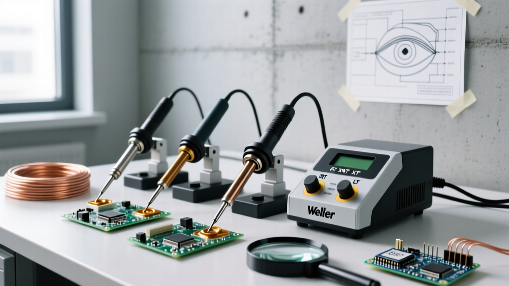
- Station Calibration: Set your temperature-controlled station (e.g., Hakko FX-951 or Weller WE1010) to exactly 150°C. Use a broad, flat chisel tip (like a Hakko T18-D24) to maximize surface area and distribute heat evenly, preventing localized hot spots.
- Pre-Tinning the Wire: Strip and pre-tin your 24 AWG wire using standard SAC305 or 60/40 solder. The bulk of the wire needs a strong mechanical bond; only the interface with the glass requires Indium.
- Applying the Indium Alloy: Using Indium-based low-temperature solder wire, feed a small amount onto the heated chisel tip. Press the pre-tinned wire into the molten Indium pool on the tip, then lower the assembly onto the ITO trace.
- Dwell Time and Cooling: Hold for exactly 3 to 5 seconds. You will see the Indium 'flash' and wet out across the ITO layer. Remove the iron and hold the wire perfectly still for 10 seconds while the 118°C alloy solidifies.
Troubleshooting Common Glass Soldering Failures
Even with the right alloys, glass soldering presents unique failure modes. Use this diagnostic matrix to correct your process.
| Failure Symptom | Root Cause | Corrective Action |
|---|---|---|
| Glass shatters or micro-cracks upon iron contact | Thermal shock from rapid localized heating. | Pre-heat the entire glass substrate on a PCB hotplate to 60°C before applying the iron. Use a wider chisel tip to spread thermal mass. |
| Solder balls up and refuses to wet the ITO | Surface contamination (skin oils) or degraded ITO layer. | Re-clean with IPA. If ITO is oxidized/degraded, lightly polish with a fiberglass scratch pen, then re-clean. |
| Joint cracks immediately upon cooling | Severe CTE mismatch causing shear stress during contraction. | Apply a thicker 'buffer' layer of pure Indium between the glass and the wire. Indium is highly malleable and absorbs CTE shear stress. |
| High electrical resistance across the joint | Flux residue trapped under the low-temp solder, or insufficient wetting. | Switch to a no-clean or flux-core Indium wire. Ensure dwell time is long enough for the flux to fully activate and boil off. |
Expert FAQ: Edge Cases in Glass Soldering
Can I use standard copper foil tape and 60/40 solder for stained glass electronics?
Yes, but with extreme caution. The traditional Tiffany copper-foil method relies on 60/40 solder melting at 183°C. To prevent the glass from cracking, you must keep the iron moving continuously and never dwell on a single spot for more than 2 seconds. However, if you are embedding microcontrollers or heat-sensitive LEDs into the stained glass, you must use a low-temperature Bismuth alloy (like CerroLow 136) for the final component connections to avoid melting the plastic housings of your electronics.
Why is Indium solder so expensive, and how can I conserve it?
Indium is a precious metal, and global supply chain constraints in 2026 keep prices high. A standard 1lb spool of 52In/48Sn can exceed $1,200. To conserve it, never use Indium to tin your wires or fill large gaps. Use standard cheap tin-lead solder for all bulk wire tinning and mechanical builds, and reserve the Indium strictly for the final 1mm interface where the metal meets the glass.
Is ultrasonic soldering safe for thin OLED display glass?
Ultrasonic soldering is generally too aggressive for ultra-thin (sub-1mm) OLED display glass. The cavitation implosions can cause microscopic spalling or delamination of the fragile organic layers beneath the glass. For OLEDs and ultra-thin displays, stick strictly to low-temperature Indium alloys applied with a highly calibrated, low-thermal-mass micro-pencil tip.