
The Science and Art of Soldered Wire Connections
In the realm of electronics, automotive wiring, and high-current drone builds, the integrity of your electrical system is only as strong as its weakest joint. While connectors and crimps have their place, soldered wire connections remain the gold standard for permanent, low-resistance, and high-reliability terminations. However, a soldered joint is not merely melted metal acting as glue; it is a complex metallurgical bond. In this comprehensive guide, we will explore the physics of wetting, the exact materials required for professional-grade terminations, and the IPC-A-610 standards that separate amateur work from aerospace-grade reliability.
The Metallurgy of Wetting and Intermetallic Compounds
To master soldered wire connections, you must understand what happens at the molecular level. Soldering is not welding. You are not melting the base metals (the copper wire and the terminal). Instead, you are facilitating a process called wetting.
When molten solder comes into contact with heated copper, a metallurgical reaction occurs, forming an Intermetallic Compound (IMC) layer—typically Cu6Sn5 (copper-tin). This IMC layer is the actual electrical and mechanical bond. According to extensive research published by IPC standards committees, the thickness of this layer is critical:
- Too thin: The joint lacks mechanical strength and may fail under vibration.
- Too thick: Caused by excessive heat or prolonged soldering times, a thick IMC layer becomes brittle and prone to micro-cracking, leading to catastrophic high-resistance failure.
Expert Insight: The ideal IMC layer in a standard Sn63Pb37 soldered wire connection is between 1 to 3 microns thick. This is achieved by applying the correct thermal profile: reaching the solder's liquidus temperature quickly, maintaining it for just 2 to 4 seconds, and allowing the joint to cool undisturbed.
Material Selection: Alloys, Fluxes, and Wire Prep
The year 2026 has brought advancements in flux chemistry and temperature-controlled iron algorithms, but the fundamental materials remain consistent. Choosing the right combination is vital for your specific application.
1. Solder Alloys
For general DIY, automotive, and non-RoHS commercial electronics, Sn63Pb37 (63% Tin / 37% Lead) remains the undisputed champion. It is a eutectic alloy, meaning it transitions directly from solid to liquid at a precise 183°C (361°F) without a plastic (semi-solid) state. This eliminates the risk of "disturbed joints" during cooldown. For commercial manufacturing or environmentally regulated projects, SAC305 (Tin/Silver/Copper) is the standard lead-free alternative, though it requires higher iron temperatures (liquidus at 217°C-220°C) and wets less readily than leaded solder.
2. Flux Chemistry
Flux is arguably more important than the solder itself. It removes copper oxidation and reduces surface tension. For wire connections, a Rosin Mildly Activated (RMA) flux, such as the industry-standard Kester 245, provides excellent wetting and leaves a residue that is non-corrosive and electrically insulating. Avoid highly activated (RA) or water-soluble acid fluxes for electrical wire connections, as trapped residues will cause galvanic corrosion over time.
3. Tooling and Thermal Mass
Attempting to solder AWG 12 or AWG 10 wire with a cheap 40W pencil iron is a recipe for cold joints. The copper wire acts as a massive heat sink. You need a temperature-controlled station with high thermal recovery. The Hakko FX-888D (typically around $115) or the portable, PD-powered Pinecil V2 (around $26) equipped with a heavy-duty TS100/C115 tip are excellent choices. For massive battery cables (AWG 8 to 4/0), a high-wattage station like the Weller WT1010 (100W) or a dedicated butane torch with a soldering iron attachment is required.
Step-by-Step Execution for Flawless Joints
Follow this exact sequence to ensure IPC-compliant soldered wire connections every time. As outlined in the foundational tutorials at Adafruit's Guide to Excellent Soldering, preparation dictates the outcome.
- Strip and Inspect: Use precision wire strippers (like the Klein Tools 11055) to remove insulation. Never nick the copper strands; a nicked strand creates a stress fracture point that will snap under vibration.
- Mechanical Mating: If splicing two wires, use a Western Union splice or a lineman's splice to provide mechanical strength before the solder is even applied. Solder should never bear the mechanical load of the wire.
- Pre-Tinning: Apply a small amount of flux and tin both the wire ends and the terminal separately. The strands should be fully encapsulated in solder, but the solder must not wick all the way up to the insulation jacket.
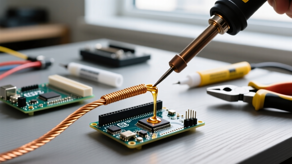
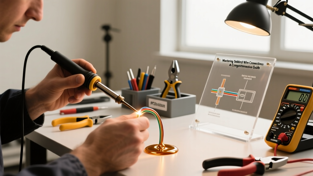
- Heat and Flow: Mate the pre-tinned components. Apply the iron tip to the thickest part of the copper mass, not directly to the solder. Feed the solder into the joint, not onto the iron tip. Once the solder flows smoothly into the strands via capillary action, remove the heat immediately.
- Undisturbed Cooldown: Hold the wire perfectly still for 3-5 seconds. Blowing on the joint can cause rapid cooling, resulting in a frosty, brittle "cold joint."
- Insulation: Slide dual-wall, adhesive-lined heat shrink (such as 3M EPS300) over the joint and apply heat. The inner adhesive layer will melt and seal out moisture, preventing capillary corrosion.
Soldered Wire Connections vs. Crimping: A 2026 Comparison
While soldering is excellent for permanent, low-profile connections, modern high-vibration environments (like EV battery packs or off-road vehicles) often favor crimping. Here is how the two methods stack up for wire-to-wire and wire-to-terminal terminations.
| Termination Method | Vibration Resistance | Tool Cost (2026 Avg) | Current Capacity | Best Use Case |
|---|---|---|---|---|
| Soldering | Moderate (brittle if IMC is thick) | $30 - $150 (Iron + Consumables) | Excellent (if 100% wetted) | PCB wiring, audio, drones, static automotive sensors |
| Crimping | Excellent (cold weld) | $80 - $300 (Quality Ratchet Tools) | Excellent | EV battery lugs, engine bay wiring, aerospace |
| Solder + Crimp | Variable (can trap flux) | $110 - $450 (Both toolsets) | Excellent | Marine environments (if sealed correctly) |
Note: Never solder a wire directly to a crimp terminal designed for bare wire. The solder will wick under the crimp barrel, creating a rigid stress point right where the wire flexes, leading to rapid fatigue failure.
IPC-A-610 Standards: Inspecting Your Work
Professional electronics manufacturers grade soldered wire connections using the IPC-A-610 standard. Understanding these visual cues will help you troubleshoot your own work.
Target Condition (Class 3 / High Reliability)
- Solder completely wets the wire strands and terminal.
- The fillet is smooth, shiny, and concave (a smooth "cove" shape).
- The contour of the wire strands is slightly visible through the solder fillet.
- Insulation is completely free of burns, scorching, or solder wicking.
Defect Conditions (Immediate Rework Required)
- Cold Joint: Dull, gray, and lumpy appearance. Caused by insufficient heat or moving the joint during solidification. Results in high electrical resistance.
- Insufficient Wetting: Solder balls up on the wire rather than flowing into the strands. Caused by oxidation, lack of flux, or contaminated copper.
- Disturbed Joint: A frosty, crystalline, or cracked surface. Caused by moving the wire before the solder fully crystallized.
- Solder Wicking: Solder travels up the wire strands under the insulation jacket. This makes the wire rigid and prone to snapping at the insulation edge.
Troubleshooting Edge Cases and Heavy Gauge Wires
One of the most common frustrations for DIYers is attempting to solder heavy-gauge battery cables (AWG 4 to AWG 1/0). Standard irons simply cannot overcome the thermal mass of the copper. If your iron's temperature drops below the solder's liquidus point upon contact, you will create a massive cold joint.
The Solution: Use the "pre-heat and thermal soak" method. Strip the heavy wire and apply generous RMA flux. Use a heat gun to gently warm the copper terminal and wire to about 100°C before applying the soldering iron. This reduces the thermal delta, allowing your iron to focus on melting the solder rather than heating the entire mass of the copper cable from room temperature. Alternatively, for AWG 2 and larger, abandon the soldering iron entirely and use a high-quality hydraulic crimp tool with closed-end copper lugs, followed by adhesive heat shrink.
Final Thoughts on Long-Term Reliability
Mastering soldered wire connections requires a shift in mindset: you are managing thermal energy and surface chemistry, not just melting metal. By respecting the metallurgy of the intermetallic compound, utilizing the correct flux, and adhering to IPC visual standards, your terminations will outlast the devices they power. Whether you are building a custom FPV drone harness or rewiring a classic car, the principles of wetting, thermal mass, and proper insulation remain your ultimate guide to electrical reliability.