
The Physics of a Perfect Wire Splice
When soldering two wires together, a common and catastrophic beginner mistake is treating solder as a structural adhesive. Solder is not glue; it is an electrical bridge. According to the stringent NASA Workmanship Standards for wire splicing, a soldered joint must never bear the mechanical load of the connection. The mechanical splice (the physical intertwining of the copper strands) must provide 100% of the tensile strength, while the solder provides the low-resistance electrical path and environmental seal.
At a microscopic level, proper heating creates an Intermetallic Compound (IMC) layer between the copper wire and the tin alloy. An ideal IMC layer is roughly 1 to 2 microns thick. If you apply too much heat for too long, the IMC layer grows excessively thick, becoming brittle and prone to micro-fractures under vibration. Conversely, insufficient heat results in a 'cold joint' where the solder merely sits on the surface without metallurgical bonding.
Essential Tool Loadout for 2026
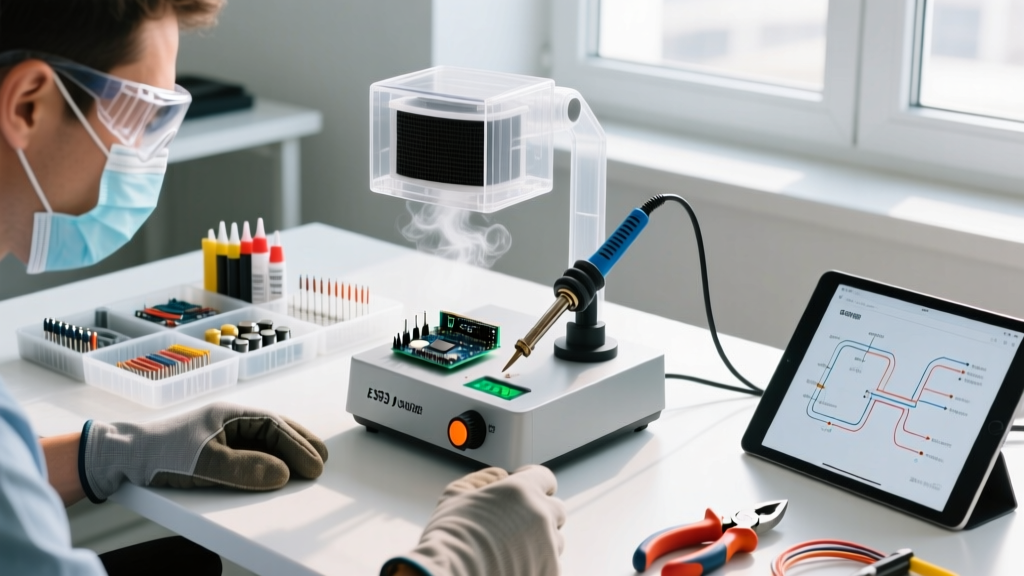
To achieve reliable, IPC-compliant wire splices, you need precise thermal control. The era of cheap, unregulated wall-wart irons is over. Here is the optimal 2026 loadout for DIYers and professionals:
- Soldering Station (Budget): Pinecil V2 (~$26). Powered by PD/USB-C, it recovers heat in seconds. Use the TS-C4 (bevel) or TS-I (needle) tip for 22-18 AWG wire.
- Soldering Station (Pro): Weller WE1010NA (~$115). Features a 70W heating element and zero-crossing switching to prevent thermal overshoot. The ETA (0.031'') tip is perfect for wire splicing.
- Solder Alloy: For general electronics and automotive DC wiring, Kester 44 63/37 (Sn/Pb) eutectic wire (0.031'' diameter) remains the gold standard due to its sharp melting point (183°C) and superior wetting. For RoHS-compliant or high-temp environments, use SAC305 (96.5% Sn, 3% Ag, 0.5% Cu).
- Flux: MG Chemicals 8341 No-Clean Tacky Flux. Never rely solely on the rosin core inside the solder wire when splicing; supplementary flux is mandatory for oxidized wire.
- Insulation: 3M FP-301 Adhesive-Lined Heat Shrink (3:1 shrink ratio). The inner thermoplastic adhesive melts and seals out moisture, preventing galvanic corrosion.
Mechanical Splice Comparison Matrix
Before any solder flows, the wires must be mechanically joined. The choice of splice depends on the wire gauge, spatial constraints, and tensile requirements.
| Splice Type | Best Application | Tensile Strength | Prep & Execution |
|---|---|---|---|
| Western Union (Lineman) | Inline splices, 18-24 AWG solid or stranded | Very High | Strip 3/4'', cross wires, twist 5-6 times each side. |
| Pigtail (Rat Tail) | Joining wires in a junction box, low stress | Low | Strip 1'', align parallel, twist together with pliers. |
| Hook Splice | Heavy gauge (14-10 AWG), high-vibration | High | Strip 1.5'', hook strands together, crimp, then solder. |
| Lap Splice | Thick battery cables, high-current DC | Medium | Strip 2'', overlap parallel, bind with bare copper wire. |
Step-by-Step Execution: The Western Union Splice
The Western Union splice is the most versatile and reliable method for soldering two wires together in inline applications. Here is the precise methodology:
1. Preparation and Stripping
Slide a piece of adhesive-lined heat shrink onto one of the wires before stripping. Strip exactly 3/4 inch (19mm) of insulation from both wires using precision wire strippers (like the Knipex 12 42 195). Avoid nicking the copper strands, as nicks create stress risers that will snap under vibration.
2. The Mechanical Twist
Cross the two stripped ends at a 45-degree angle. Using your fingers, twist the right wire tightly around the left wire for 5 to 6 turns. Repeat with the left wire around the right. Use lineman's pliers to grip the very ends of the twisted tails and pull them taut, ensuring the coils are tightly bound with no gaps.
Pro Tip: Trim the sharp tips of the twisted tails flush with diagonal cutters. Protruding sharp ends will eventually pierce through the heat shrink and cause a short circuit.
3. Tinning and Fluxing
Apply a small dab of tacky flux over the entire twisted joint. Set your iron to 350°C (662°F) for 63/37 leaded solder, or 385°C (725°F) for SAC305 lead-free. Tin the tip of your iron with a small amount of fresh solder to create a thermal bridge.
4. The Solder Flow
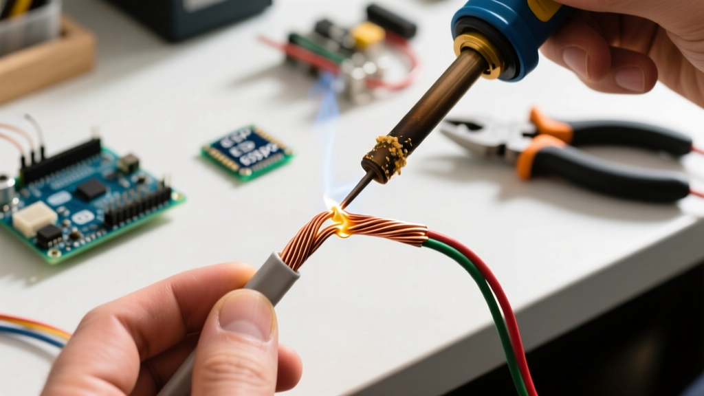
Place the tinned iron tip directly against the copper wire (not the solder). Count to two seconds to allow the copper to reach flow temperature. Touch your solder wire to the opposite side of the joint from the iron. Capillary action will draw the molten solder through the twisted strands. You are looking for a smooth, concave fillet that completely wets the wire. Total dwell time should not exceed 4 seconds.
5. Cooling and Inspection
Remove the iron and hold the wires perfectly still for 5 seconds. A 63/37 eutectic alloy transitions from liquid to solid instantly, but disturbing it during the plastic phase creates a disturbed joint (characterized by a dull, grainy, or frosty appearance). Once cool, clean the residual flux with 99% isopropyl alcohol.
Troubleshooting Common Wire Soldering Defects
Even experienced technicians encounter issues when soldering wires. Refer to this diagnostic guide based on SparkFun's soldering defect taxonomy:
- Cold Joint (Solder balls up, refuses to flow): The wire was not hot enough. This happens when using an iron with too low a wattage for thick (14 AWG+) wire, or failing to use flux on oxidized copper. Fix: Add fresh flux, increase iron temp by 15°C, and reflow.
- Solder Wicking (Solder travels under the insulation): The wire was stripped too short, or the iron was held too close to the jacket. This makes the wire stiff near the joint, leading to fatigue failure. Fix: Hold the iron in the center of the splice; let capillary action do the work.
- Burnt Flux / Charred Insulation: Dwell time exceeded 5 seconds, or the temperature was set above 420°C. The flux burns into a hard, acidic carbon residue that promotes long-term corrosion. Fix: Use a larger iron tip to transfer heat faster at lower temperatures.
Environmental Sealing: The Final Step
A flawless solder joint will fail in the field if exposed to moisture and oxygen. Sliding the pre-positioned 3:1 adhesive-lined heat shrink over the joint, apply heat starting from the center and moving outward. The adhesive lining will melt and squeeze out the ends slightly, indicating a complete environmental seal. This final step transforms a fragile electrical connection into a rugged, automotive-grade harness ready for real-world deployment.