
The Hidden Dangers of HDMI Rework
When repairing motherboards, graphics cards, or AV receivers, soldering an HDMI port is widely considered one of the most high-risk procedures in micro-soldering. A standard Type-A HDMI connector features 19 pins with a punishing 0.5mm pitch. Beyond the mechanical difficulty, the pins connect directly to highly sensitive TMDS (Transition Minimized Differential Signaling) transceivers and GPU encoding ICs. A single mistake—whether thermal, electrical, or chemical—can result in catastrophic pad delamination, fried silicon, or high-frequency signal degradation.
This guide details the strict safety best practices for soldering HDMI ports, focusing on protecting both the operator and the delicate PCB architecture. We will cover ESD mitigation, thermal profiling, and the precise techniques required to maintain signal integrity in 2026's high-bandwidth HDMI 2.1 environments.
Workspace Safety: ESD and Fume Mitigation
Before your iron even powers on, your workspace must be configured to handle the specific vulnerabilities of HDMI circuitry. The TMDS data lanes operate at high frequencies (up to 12 Gbps per lane for HDMI 2.1) and are extremely susceptible to Electrostatic Discharge (ESD).
ESD Protection Protocols
According to the ANSI/ESD S20.20 standard, protecting sensitive electronics requires a controlled grounding path. An HDMI encoder IC can be destroyed by an ESD event as low as 30 volts—far below the threshold of human perception.
- Wrist Straps: Always wear a wired ESD wrist strap connected to a common point ground with a 1-megohm safety resistor. Wireless straps are ineffective for high-frequency digital IC protection.
- Mat Resistance: Your workbench mat must be dissipative, typically ranging between 1.0 x 10^6 and 1.0 x 10^9 ohms. Insulative mats will trap charges, while purely conductive mats can cause rapid discharge spikes.
- Ionizers: If you are working on flexible PCBs or using Kapton tape to mask surrounding components, static will build up rapidly. An overhead ionizer is mandatory to neutralize localized charges.
Fume Extraction and Respiratory Safety
Soldering HDMI ports requires copious amounts of flux to manage the 0.5mm pitch. When rosin-based or synthetic fluxes are heated to 350°C, they release volatile organic compounds (VOCs) and particulate matter, including formaldehyde and toluene. The Hakko fume extraction guidelines emphasize that standard desk fans merely blow these toxins into your breathing zone. You must use a localized HEPA and activated carbon extraction unit positioned 6 to 8 inches from the soldering zone to capture colophony at the source.
Thermal Management: Preventing Pad Delamination
The most common physical failure when soldering an HDMI port is pad lift (delamination). The FR-4 fiberglass substrate of a PCB has a Glass Transition Temperature (Tg) typically between 130°C and 170°C. While the soldering iron tip is at 350°C, the goal is to heat the pad and pin to the solder's liquidus point (around 217°C for SAC305 lead-free) as quickly as possible without lingering.
Using an undersized tip forces the operator to increase the station temperature and dwell time, which soaks the entire HDMI shell and melts the internal plastic dielectric of the connector. Conversely, a properly thermal-massed tip transfers heat instantly.
Optimal Tool Selection
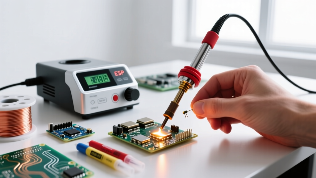
For HDMI Type-A ports, abandon standard chisel tips. You need a Micro-Knife or Mini-Hoof tip. For example, the JBC C245-945 (Mini-Knife) or the Hakko B2032 (Micro-Knife) provide the edge geometry necessary to drag-solder 0.5mm pins without bridging. Expect to pay between $45 and $65 for genuine OEM tips; cheap clones suffer from poor thermal recovery and will cause cold joints.
| Station Type | Tip Geometry | Target Temp (Lead-Free) | Target Temp (Leaded) | Max Dwell Time / Pin |
|---|---|---|---|---|
| JBC CD-2BE (Active Tip) | C245-945 Mini-Knife | 330°C - 340°C | 290°C - 300°C | 1.5 - 2.0 Seconds |
| Hakko FX-951 (Active Tip) | B2032 Micro-Knife | 340°C - 350°C | 300°C - 310°C | 2.0 - 2.5 Seconds |
| Pinecil V2 (Portable) | TS-I010 (Mini-Knife) | 350°C - 360°C | 310°C - 320°C | 2.5 - 3.0 Seconds |
Step-by-Step Safe Soldering Protocol
Follow this exact sequence to ensure mechanical stability and electrical safety. This protocol assumes the old HDMI port has been safely desoldered using a hot air rework station at 380°C with minimal prying force.
- Pad Preparation: Clean the 19 PCB pads using 99% Isopropyl Alcohol (IPA) and lint-free swabs. Apply a thin layer of high-tack, no-clean tacky flux (e.g., Amtech NC-559-V2-TF, approx. $35 per syringe) using a precision needle tip.
- Alignment and Tack: Seat the new HDMI port. Under a stereo zoom microscope (minimum 10x magnification), tack pin 1 and pin 19 to lock the connector in place. Verify alignment on the opposite side of the port.
- Shell Grounding: Solder the large metal shielding tabs first. These act as massive heat sinks. Use a larger chisel tip (like a JBC C245-112) at 380°C to quickly flow solder into the ground planes. Doing this first prevents the thermal mass of the shell from stealing heat during the delicate pin soldering phase.
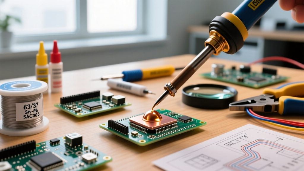
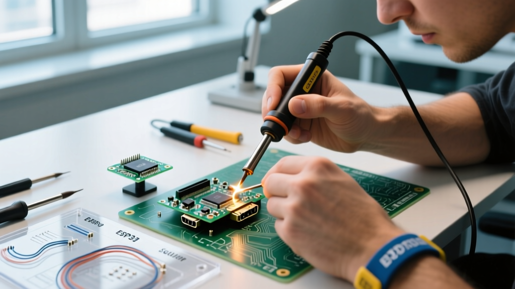
- Drag Soldering: Switch back to the micro-knife tip. Load the knife edge with a small bead of 63/37 leaded solder (leaded is vastly superior for hand-rework due to its lower melting point and superior wetting). Drag the knife across the 19 pins at a 45-degree angle, letting capillary action pull the solder into the vias.
- Inspection: Inspect under magnification. You are looking for the IPC-A-610 standard requirement of a smooth, concave fillet with visible wetting on every pin.
Handling 0.5mm Pitch Short Circuits
Bridging is almost guaranteed on your first few attempts. Never use the iron to physically wipe the solder away. This smears solder into the microscopic gaps and risks lifting the pads. Instead, apply fresh liquid flux over the bridged pins, place a high-quality desoldering wick (e.g., Chemtronics 80-1-5), and press down gently with a clean, fluxed iron tip. The wick will absorb the excess solder via capillary action in roughly 2 seconds.
Critical Warning: Pay extreme attention to Pins 18 (+5V Power) and 19 (Hot Plug Detect). If you bridge these two pins with solder, the 5V line will feed directly back into the GPU's HPD logic gate the moment a cable is plugged in, instantly destroying the graphics card's HDMI controller.
Signal Integrity and Flux Residue
A frequently overlooked safety hazard in HDMI rework is chemical, not thermal. HDMI 2.1 relies on FRL (Fixed Rate Link) signaling, pushing data rates up to 48 Gbps. At these microwave frequencies, the PCB traces act as transmission lines with strict impedance requirements (typically 100 ohms differential for TMDS pairs).
If you leave thick, acidic, or highly conductive water-soluble flux residue between the 0.5mm pins, it introduces parasitic capacitance and leakage resistance. This alters the impedance of the differential pairs, causing signal reflection, bit errors, and the dreaded 'black screen' or 'sparkles' on 4K displays. Always clean the port thoroughly with IPA and a soft-bristle ESD-safe brush, or use a verified no-clean flux that is specifically rated for high-frequency RF/microwave applications.
Frequently Asked Questions
Can I use hot air to solder a through-hole HDMI port?
No. While hot air is excellent for removing the port, using it to solder a through-hole HDMI port is highly unsafe. The airflow will blow the lightweight connector out of alignment, and the prolonged 350°C+ ambient heat will melt the internal plastic tongue of the HDMI receptacle, ruining the pin geometry. Always use a contact iron for the final soldering.
My HDMI pads lifted during desoldering. Is the board dead?
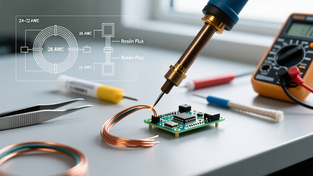
Not necessarily. If the copper pad lifts but the underlying via is intact, you can scrape back the solder mask on the trace leading to the via, tin the exposed copper, and use a 0.1mm enameled copper jumper wire to reconnect the new HDMI port pin to the trace. Secure the wire with UV-curable solder mask resin to prevent mechanical stress.
Is it safe to use lead-free solder for HDMI repairs?
While you can use lead-free (SAC305), it is not recommended for manual rework. Lead-free solder requires higher temperatures (increasing the risk of thermal damage to the PCB) and has a higher surface tension, which makes drag-soldering 0.5mm pitches much more prone to bridging. Mixing leaded 63/37 solder with the factory lead-free pads creates a reliable, lower-temperature joint that is perfectly safe for consumer electronics repair.