
The Core Dilemma: Manual vs. Robotic Soldering in 2026
As electronics manufacturing transitions toward higher-density PCBs and stricter lead-free compliance, the margin for human error in soldering has virtually evaporated. The shift to SAC305 and SAC405 lead-free alloys requires precise thermal profiling; melting points hover around 217°C to 220°C, and the wetting window is significantly narrower than legacy Sn63/Pb37 solders. For lab managers, contract manufacturers (CMs), and high-volume prosumers, the question is no longer if automation is superior, but when the capital expenditure (CapEx) justifies the operational savings.
This decision framework cuts through the marketing noise. We will evaluate the exact thresholds for investing in robotic soldering systems—ranging from Cartesian wire-harnessing robots like the Janome JR3000 series to dedicated through-hole/selective systems like the JBC RS-200 Robotic Soldering System—versus maintaining a fleet of high-end manual stations.
The 2026 Baseline Rule: If your facility produces fewer than 3,000 solder joints per day, or if your board geometry changes weekly, robotic soldering will yield a negative ROI due to programming overhead. If you exceed 5,000 homogeneous joints daily, automation is mandatory for IPC Class 3 compliance.
The 4-Pillar Decision Framework
To determine if your production line is ready for robotic integration, audit your workflow against these four critical pillars.
Pillar 1: Production Volume & Takt Time
Manual soldering relies on operator rhythm. A highly skilled technician using a JBC CD-2BQF station can complete a standard through-hole joint in 3.5 to 4.5 seconds. However, human fatigue degrades this cycle time by 15-20% after the fourth hour of a shift. Robotic systems maintain a relentless takt time. The JBC RS-200, for instance, averages 1.8 to 2.5 seconds per joint, inclusive of Z-axis descent, localized preheat, solder wire feeding, and retraction.
- Low Volume (Prototyping/NPI): Stick to manual. Programming a Cartesian robot for a 50-board prototype run takes longer than simply soldering it by hand.
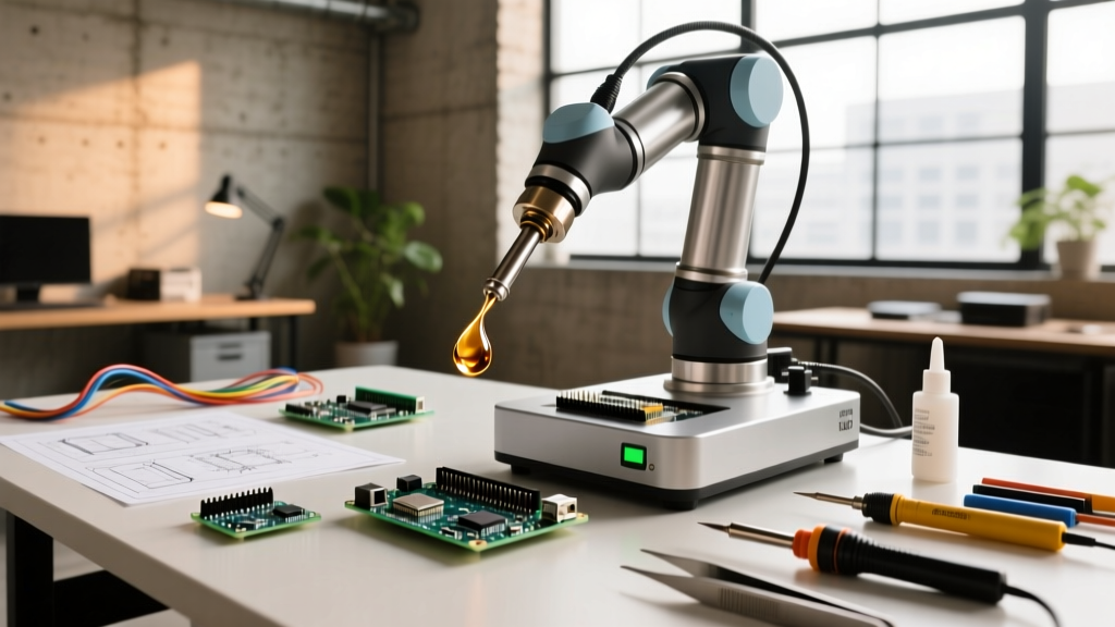
- Medium Volume (Batch Manufacturing): Consider collaborative robotic arms (cobots) equipped with soldering end-effectors for flexible cell layouts.
- High Volume (Continuous Run): Dedicated XYZ-axis robotic soldering cells are mandatory to meet takt time requirements.
Pillar 2: Joint Geometry & Thermal Mass Variance
Robotic soldering excels at repetitive, predictable thermal masses. If your PCB features a mix of 0603 surface mount pads (requiring minimal heat) adjacent to heavy copper ground planes (requiring massive thermal transfer), manual operators intuitively adjust dwell time and iron pressure. Robots require explicit, line-by-line programming for these variances. If your board has high thermal mass variance, you must invest in robotic systems with closed-loop thermocouple feedback or laser preheating modules, which increases CapEx by 30% to 40%.
Pillar 3: Wire Harnessing and 3D Soldering
For wire-to-board connections, 2D selective soldering machines fail. You need 4-axis or 6-axis Cartesian robots. Systems like the Janome JR3000 series utilize vision systems to locate the exact insertion point of a pre-stripped wire, apply flux, and execute a 3D soldering path. If your product relies heavily on wire harnesses (e.g., automotive sub-assemblies, aerospace telemetry), robotic soldering reduces wire-pull test failures by eliminating the 'cold-shock' effect caused by manual wire movement during the cooling phase.
Pillar 4: IPC-A-610 Compliance and Traceability
Meeting IPC-A-610 Class 3 standards for high-reliability electronics requires perfect wetting, specific fillet geometries, and zero flux splatter on adjacent components. Robotic systems provide programmable solder wire feed rates (measured in mm/sec) and precise nitrogen-assisted environments to prevent oxidation. Furthermore, modern robotic cells log every joint's temperature profile and dwell time to a local SQL database, providing the digital traceability required by aerospace and medical device auditors.
CapEx vs. OpEx: The Financial Breakdown
Understanding the true cost of ownership requires looking beyond the initial hardware purchase. Below is a comparative analysis of a standard manual setup versus mid-tier and high-tier robotic solutions based on 2026 market pricing.
| Metric | Manual Fleet (e.g., JBC CD-2BQF x 3) | Cartesian Robot (e.g., Janome JR3000) | Dedicated System (e.g., JBC RS-200) |
|---|---|---|---|
| Initial CapEx | $2,400 - $3,000 | $7,500 - $12,000 | $14,000 - $18,500 |
| Tip Replacement Cost | $55/tip (High wear rate) | $65/tip (Medium wear rate) | $70/tip (Low wear rate) |
| Tip Lifespan | 20,000 - 30,000 joints | 60,000 - 80,000 joints | 100,000+ joints |
| Rework / Scrap Rate | 1.5% - 3.0% | 0.5% - 1.0% | < 0.2% |
| Operator Requirement | 3 Skilled Technicians | 1 Loader / 1 Programmer | 1 Loader (Automated Feed) |
Note: OpEx savings in tip longevity on dedicated systems are driven by automated sleep modes and precise Z-axis control, which prevents the microscopic pad gouging that destroys manual tips.
Edge Cases: When Robotic Soldering Fails
Automation is not a panacea. As an electrical engineer or production manager, you must anticipate the specific failure modes inherent to robotic soldering cells. Ignoring these will result in catastrophic yield drops.
- Flux Carbonization on the Feed Tube: In robotic systems, the solder wire is fed through a PTFE or metal guide tube directly to the joint. If the retraction speed is too slow, rosin-based flux (like ROL0 or ROL1) can boil back up into the tube, carbonize, and cause wire jamming. Solution: Implement a programmable 'wire retract and clean' cycle after every 50 joints.
- Z-Axis Calibration Drift and Pad Gouging: PCBs are rarely perfectly flat; warping occurs during wave soldering or reflow. If a robot's Z-axis is strictly position-controlled rather than force-controlled, a warped board will result in the soldering tip crushing the copper pad. Solution: Invest in systems with active Z-axis load-cell feedback that halts descent upon detecting 15-20 grams of resistance.
- Solder Balling from Inadequate Preheat: Robots move fast. If the system applies solder wire before the pad reaches the liquidus temperature of the SAC305 alloy, the flux activates and spatters, creating microscopic solder balls that can migrate under BGA components and cause shorts. Solution: Utilize robotic systems with integrated hot-air or laser preheat modules that dwell for 400-600ms before wire feed.
Step-by-Step Implementation Checklist
If your facility meets the volume and complexity thresholds outlined above, follow this sequential framework to integrate robotic soldering into your line:
- Audit Thermal Mass Profiles: Map your PCB into three thermal zones (low, medium, high mass). This dictates whether you need a standard 60W robotic iron or a 130W high-power variant.
- Select the Wire Feed Mechanism: Choose between push-only feeders (good for standard 0.8mm wire) and push-pull feeders (mandatory for ultra-fine 0.3mm wire or rigid lead-free alloys).
- Program Wetting Profiles: Do not rely on factory presets. Program a specific dwell time, feed rate (mm/sec), and retraction angle for every unique joint geometry on the board.
- Validate Against IPC Standards: Run a 100-board pilot batch. Section 10 random joints via microsectioning to inspect intermetallic compound (IMC) layer thickness, ensuring it falls within the optimal 1.0 to 3.0 microns range.
Final Verdict
Transitioning to robotic soldering is a definitive leap from 'craftsmanship' to 'manufacturing science.' For high-mix, low-volume environments, the programming overhead of robotic cells remains a bottleneck, making advanced manual stations the superior choice. However, for facilities pushing past 5,000 daily joints, dealing with unforgiving lead-free alloys, or requiring stringent digital traceability for IPC Class 3 compliance, the ROI of a dedicated system like the JBC RS-200 is typically realized within 11 to 14 months through scrap reduction and labor reallocation. Evaluate your takt time, respect the thermal dynamics of your PCBs, and let the data dictate your automation strategy.