
Redefining the 'Soldering Machine' for Modern Prototyping
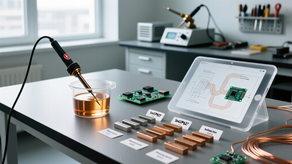
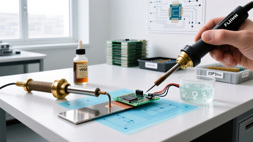
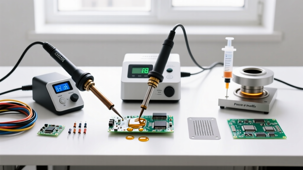
When engineers and hobbyists ask how to use a soldering machine, they are rarely referring to the massive, conveyor-fed wave soldering systems found in high-volume manufacturing. In the 2026 landscape of DIY electronics, prosumer prototyping, and small-batch assembly, the term 'soldering machine' encompasses a triad of advanced desktop tools: smart digital soldering stations, precision hot air rework systems, and programmable mini-reflow hotplates.
Mastering these machines requires moving beyond simple 'plug-and-melt' tactics. It demands an understanding of thermal profiling, metallurgical wetting phases, and substrate heat dissipation. Whether you are assembling a custom ESP32 sensor node or reworking a dense 0.5mm pitch FPGA, this comprehensive guide will walk you through the exact parameters, techniques, and failure-mode mitigations required for professional-grade results.
The 2026 Prosumer Soldering Machine Ecosystem
Before applying heat, you must select the right machine architecture for your specific PCB density. Below is a comparison of the dominant machine categories used in modern labs and maker spaces.
| Machine Category | Top 2026 Models | Price Range | Primary Use Case |
|---|---|---|---|
| Smart Digital Station | Hakko FX-888D, Weller WE1010NA | $110 - $135 | Through-hole (THT), fine-pitch drag soldering, wire tinning. |
| Hot Air Rework Machine | Quick 861DW, Sugon 8620DX | $240 - $290 | Multi-layer board rework, QFN/BGA removal, heat-shrink tubing. |
| Mini Reflow Hotplate | FNIRSI HS-01, Miniware MHP50 | $60 - $95 | Batch SMD reflow, rapid prototyping of 0402/0603 passives. |
| USB-C Smart Iron | Pinecil V2, Sequre SI03 | $26 - $45 | Field repairs, portable labs, quick THT joints. |
Phase 1: Thermal Profiling and Material Selection
The most common mistake when learning how to use a soldering machine is setting the temperature dial arbitrarily. Your machine's setpoint must be dictated by the solder alloy's liquidus temperature and the thermal mass of your specific PCB.
Alloy-Specific Temperature Baselines
- Sn63/Pb37 (Leaded Eutectic): Melts at 183°C. For a standard digital station like the Weller WE1010NA, set the tip temperature to 315°C - 330°C. This provides the necessary thermal delta to transfer heat through the flux activation phase without boiling the flux instantly.
- SAC305 (Lead-Free): Melts at 217°C. Requires a higher working temperature of 350°C - 370°C. SAC305 has poorer wetting characteristics than leaded solder; compensating with aggressive flux is mandatory.
Expert Insight: Never exceed 380°C on standard copper-plated tips when using SAC305. High temperatures accelerate the dissolution of the iron plating on your tip, leading to pitting and catastrophic failure within weeks. If you need more heat transfer, switch to a chisel tip with a larger thermal mass rather than turning up the dial.
Phase 2: Execution Techniques for SMD and THT
Different component packages demand entirely different machine handling techniques. Here is how to execute the two most critical operations in PCB assembly.
Technique A: Drag Soldering Fine-Pitch ICs (0.5mm Pitch TQFP/QFP)
When soldering a microcontroller with 48 or 64 pins spaced at 0.5mm, placing individual solder joints is impossible. Drag soldering utilizes the surface tension of molten solder to self-align the component.
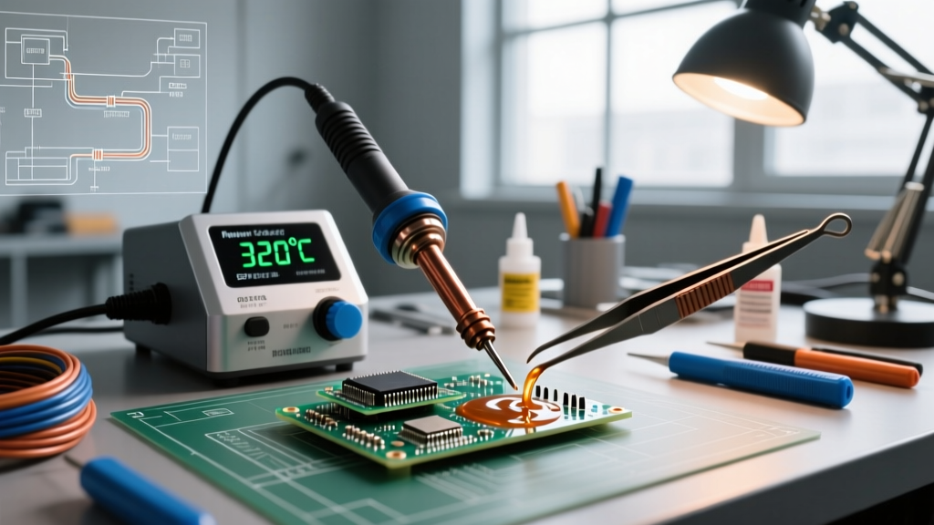
- Prep & Tack: Apply a thin layer of Amtech NC-559-V2-TF no-clean tacky flux to the pads. Align the IC and tack two diagonal corner pins using a 0.4mm conical tip at 320°C.
- Flux Flood: Apply a generous bead of liquid or gel flux across the entire row of pins. Flux is the actual 'machine' doing the work here—it prevents bridging by reducing surface tension.
- The Drag: Load a 1.6mm or 2.4mm hoof (bevel) tip with a moderate amount of Kester 245 RMA solder. Tilt the board at a 45-degree angle. Drag the tip slowly across the pins, allowing gravity and capillary action to pull the solder into the gaps.
- Wick Cleanup: If bridges form, do not panic. Apply fresh flux and drag a high-quality copper desoldering braid (e.g., Goot Wick CP-3015) across the bridged pins. The braid will absorb the excess solder while leaving the pads perfectly wetted.
Technique B: Programmable Mini-Reflow for Passives
For populating boards with dozens of 0402 (1.0mm x 0.5mm) resistors and capacitors, a mini-reflow machine like the FNIRSI HS-01 is vastly superior to hand soldering.
- Use a stainless steel stencil to apply SAC305 Type 4 solder paste (which features smaller powder particles essential for micro-pads).
- Place components using precision tweezers. The tackiness of the paste holds them in place.
- Program the hotplate with a standard reflow profile: Preheat (ramp to 150°C over 90 seconds to outgas flux), Soak (hold at 150°C for 60 seconds to equalize board temperature), and Reflow (ramp to 240°C, hold for 45 seconds above the 217°C liquidus line, then power off to cool).
Critical Failure Modes and Edge Cases
Even with premium equipment, physics can work against you. Understanding these failure modes is what separates novices from experts adhering to IPC soldering standards for Class 2 and Class 3 electronics.
- Tombstoning on 0402/0603 Passives: This occurs when one pad heats faster than the other, causing the surface tension of the melting solder to pull the component upright. Fix: Ensure your PCB design includes thermal relief on ground pads, or use a hot air preheater to bring the entire board to 100°C before applying localized heat.
- Thermal Pad Starvation (QFN Components): Quad Flat No-lead (QFN) chips feature a massive exposed thermal pad on the bottom. If soldered with an iron, the internal ground planes act as heat sinks, resulting in a cold, dry joint. Fix: You must use a hot air rework machine or a bottom-side preheater to achieve uniform reflow of the hidden pad.
- Delamination on Multi-Layer Boards: Applying 400°C to a via for more than 5 seconds can cause the epoxy resin in FR4 substrates to exceed its glass transition temperature (Tg), leading to internal layer separation. Fix: Limit dwell time to 3 seconds per joint. If the joint isn't flowing, stop, add flux, and reassess your tip geometry.
Machine Maintenance: Calibrating Your Digital Station
Digital readouts on soldering machines are not infallible. Over time, thermal drift and tip oxidation can cause the actual tip temperature to deviate from the screen's readout by 10°C to 15°C. For precision work, quarterly calibration is mandatory.
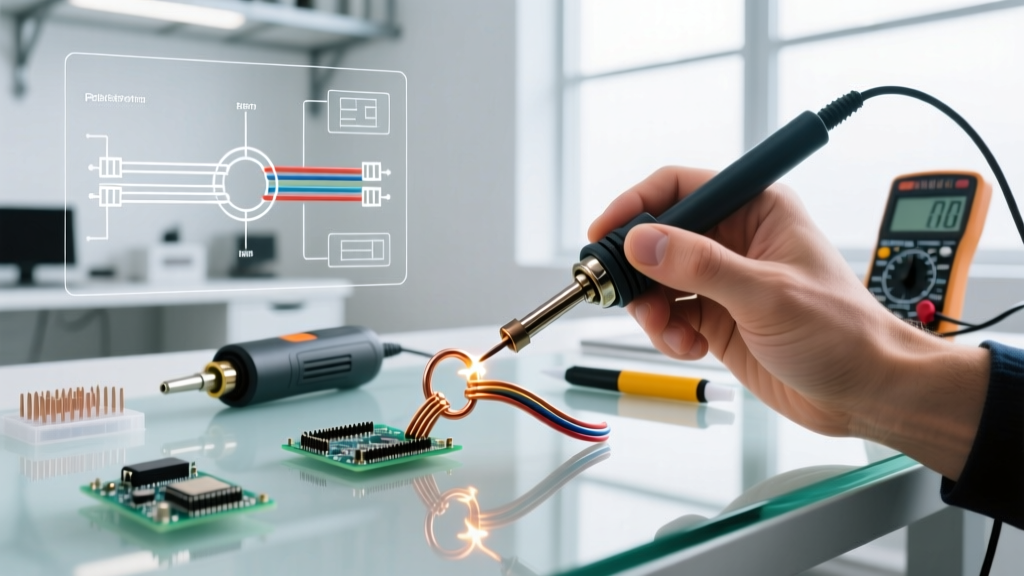
For industry standards like the Hakko FX-888D, calibration requires a digital thermocouple meter and high-temp probe tape. You can find excellent baseline tutorials on surface-mount soldering techniques and tool maintenance via community hubs. The general process involves:
- Taping the thermocouple bead directly to the flat face of a clean, tinned chisel tip using Kapton tape.
- Setting the machine to 350°C and allowing it to stabilize for 3 minutes.
- Entering the machine's hidden calibration menu (on the FX-888D, this is done by holding the UP arrow while turning the power on).
- Adjusting the digital offset until the screen matches the thermocouple's physical reading.
Summary: Precision is a Process
Learning how to use a soldering machine effectively is less about the hardware and more about managing thermal dynamics. By matching your tool (smart station vs. reflow hotplate) to the component geometry, strictly adhering to alloy-specific thermal profiles, and proactively mitigating heat-sink effects on multi-layer boards, you will achieve joints that are mechanically robust and electrically flawless. Invest in high-quality flux, maintain your tip plating, and let the metallurgy do the heavy lifting.