
The Unique Thermal Challenges of Cable Soldering
Unlike soldering surface-mount components to a PCB, cable soldering introduces complex thermal dynamics. Stranded copper wire acts as a massive heat sink, drawing thermal energy away from the joint, while the surrounding polymer insulation (PVC, PTFE, or silicone) has strict thermal degradation limits. In 2026, as consumer electronics and DIY robotics demand higher current capacities in smaller form factors, mastering the thermal balance of wire termination is critical. A poorly executed cable solder joint will fail under mechanical vibration or thermal cycling, leading to intermittent faults or catastrophic short circuits.
This comprehensive guide addresses the most frequent failure modes in cable assembly, providing actionable troubleshooting matrices, alloy comparisons, and expert-backed methodologies aligned with modern workmanship standards.
Troubleshooting Matrix: Diagnosing Cable Soldering Failures
When a cable joint fails visual inspection or mechanical pull-testing, identifying the root cause is the first step toward correction. Refer to the matrix below to diagnose common issues.
| Symptom | Root Cause | Corrective Action |
|---|---|---|
| Solder Wicking (Solder flows under the wire insulation) | Over-stripping the wire or applying the iron directly to the insulation boundary. | Strip exactly 2x the termination length. Pre-tin the wire separately before mating to the terminal. Keep the iron tip at least 2mm away from the insulation. |
| Dull, Grainy Joint (Cold Joint) | Movement during the plastic state (non-eutectic alloys) or insufficient thermal mass transfer. | Use a third-hand tool to immobilize the cable. Increase tip temperature by 20°C or switch to a heavier chisel tip for better thermal coupling. |
| Insulation Melt/Retraction | Dwell time exceeding 4 seconds, or using a tip too large, transferring radiant heat to the jacket. | Limit contact time to 2-3 seconds. Use a tip geometry that matches the wire gauge (e.g., a 1.6mm chisel for 18 AWG). |
| Brittle/Fractured Strand | Mechanical damage during stripping or using acidic (plumbing) flux that corrodes copper. | Use precision wire strippers (e.g., Hakko CHP-170). Only use rosin-based (RA/RMA) or no-clean electronic flux. |
FAQ: Wire Preparation, Flux, and Mechanical Integrity
Q: Should I crimp or solder for high-vibration cable assemblies?
This is one of the most debated topics in electrical engineering. According to the IPC/WHMA-A-620 standards for cable and wire harness assemblies, crimping is vastly superior to soldering in high-vibration environments (e.g., automotive, aerospace, drones). Solder creates a rigid, brittle transition zone between the flexible stranded wire and the solid terminal. Under harmonic vibration, the wire will work-harden and snap exactly at the edge of the solder joint. However, for static applications (e.g., desktop audio equipment, indoor IoT sensors), cable soldering is perfectly reliable provided you implement proper mechanical strain relief.
Q: Why is flux selection so critical for stranded wire?
Stranded wire has a high surface area that rapidly oxidizes when heated. Without flux, the solder will ball up and refuse to wet the copper. For cable soldering, we recommend a mildly activated rosin flux (RMA) like Kester 186 or a high-quality no-clean gel like Amtech NC-559-V2-TF. Never use plumbing paste flux; the zinc chloride will aggressively eat through the copper strands, causing high-resistance failures months later.
Expert Tip: If you are soldering high-impedance RF cables (like RG316 coaxial), you must clean "no-clean" flux residues with 99% isopropyl alcohol. Leftover flux can introduce parasitic capacitance and alter the characteristic impedance of the RF line at microwave frequencies.
Thermal Profiles: Matching Alloys to Cable Gauges
Selecting the correct solder alloy and corresponding iron temperature is non-negotiable for reliable cable soldering. The thermal mass of thick cables (14 AWG to 18 AWG) requires aggressive heat transfer, while delicate signal wires (24 AWG to 30 AWG) demand precision.
- Sn63/Pb37 (Eutectic 63/37): Melts at 183°C. Because it transitions instantly from liquid to solid without a plastic state, it is highly resistant to cold-joint fracturing if the wire is bumped. Recommended Iron Temp: 320°C - 340°C.
- SAC305 (Sn96.5/Ag3.0/Cu0.5): The 2026 industry standard for RoHS-compliant commercial manufacturing. Melts at 217°C. It requires higher thermal input and wets slightly slower than leaded solder. Recommended Iron Temp: 350°C - 380°C.
- Sn99.3/Cu0.7 (Silver-Free Lead-Free): Melts at 227°C. Often used in cost-sensitive consumer cables. It produces a dull finish and is more prone to fatigue cracking on thick, flexible cables. Recommended Iron Temp: 360°C - 390°C.
Step-by-Step Pre-Tinning for Heavy Gauge Cables
Attempting to solder a 12 AWG or 14 AWG silicone wire directly to an XT60 connector pad is a recipe for a cold joint. The massive copper strands will absorb the heat faster than the soldering iron can replenish it. You must pre-tin. Follow this sequence for flawless heavy-gauge terminations:
- Strip and Inspect: Strip 6mm of insulation. Ensure no outer strands are nicked or severed by the stripper blades.
- Apply Flux: Dip the bare copper into a pot of RMA flux or apply a small bead of flux gel. Capillary action will draw it between the strands.
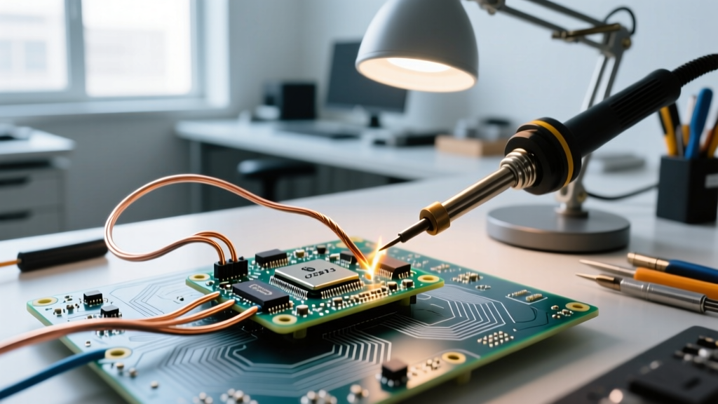
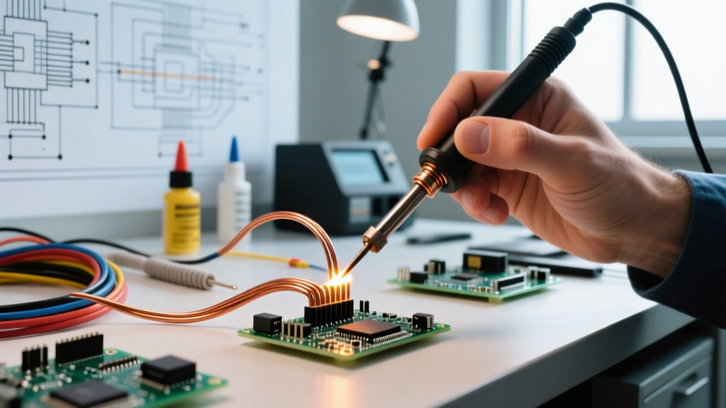
- Heat the Wire, Not the Solder: Place a large chisel tip (e.g., Hakko T18-D24) against the copper. Feed the solder wire into the copper strands, not the iron tip. When the copper reaches the melting point, the solder will wick smoothly to the insulation boundary.
- Clean and Mate: Wipe the tinned wire on a damp brass sponge. Insert it into the pre-tinned connector cup and apply heat for exactly 2 seconds to fuse the two tinned surfaces.
Modern Tooling: Active Tips vs. Smart Irons
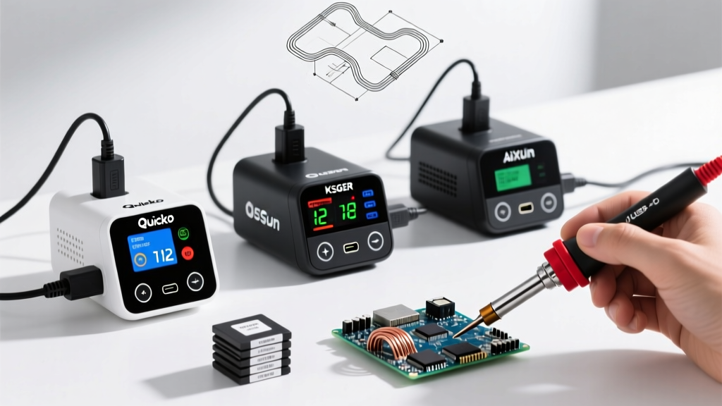
For cable soldering, thermal recovery is more important than peak temperature. In 2026, the market is divided between active-cartridge stations and smart PD-powered irons. For heavy cables (10-16 AWG), cartridge systems like the Hakko FX-951 or JBC CD-2BQF are mandatory. Their tips contain integrated heating elements that sense thermal drop and inject current directly into the tip mass, recovering from a 14 AWG heat-sink event in under 1.5 seconds. For lighter signal cables (20-28 AWG), smart irons like the Pinecil V2 (powered via USB-C PD at 65W) offer exceptional precision, rapid heat-up, and open-source temperature profiling, making them ideal for field repairs and drone wiring.
Strain Relief: The Unsung Hero of Cable Longevity
A perfect metallurgical bond will still fail if mechanical stress is transferred to the solder joint. The NASA Electronic Parts and Packaging (NEPP) Program workmanship manuals strictly mandate mechanical strain relief for all cable terminations. In modern DIY and commercial applications, this is achieved using dual-wall adhesive-lined heat shrink tubing (such as 3M EPS300). Unlike standard polyolefin tubing, dual-wall shrink features an inner layer of thermoplastic adhesive. When heated, the outer wall shrinks by 3:1, while the inner adhesive melts, flowing into the interstices of the stranded wire and the connector housing. Upon cooling, it creates a waterproof, vibration-dampening mechanical lock that ensures zero stress reaches the actual solder joint.
For further reading on advanced termination techniques and acceptability criteria, consult the Hakko USA technical guides on tip selection and thermal management, which provide excellent visual references for matching tip geometry to specific wire gauges.