
The Physics of Thermal Runaway in PCB Soldering
When a 350°C soldering iron tip touches a component lead, thermal energy does not just stay localized at the joint. It propagates rapidly through the copper lead frame and into the semiconductor die. For robust passive components, this is irrelevant. But for sensitive active components—like GaN (Gallium Nitride) transistors, CMOS logic ICs, and precision op-amps—this thermal wave can cause catastrophic latent failures. Gate oxide degradation, die attach delamination, and wire bond lift-off often occur silently, only to manifest as field failures months later.
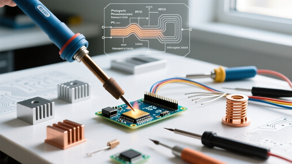
A soldering heat sink (often called a thermal shunt) acts as a parasitic thermal mass. It intercepts conductive heat flow before it reaches the component body. However, slapping any piece of metal on a lead is not enough; improper shunting can starve the joint of heat, resulting in cold, grainy solder fillets. This decision framework will guide you through material science, mechanical form factors, and application methodologies to select and use the right soldering heat sink for your specific PCB assembly needs.
The Component Vulnerability Matrix
Before selecting a tool, you must quantify the thermal threat. The IPC J-STD-001 standard outlines strict dwell time and temperature limits for various component classes. Use this matrix to determine if a heat sink is optional, recommended, or mandatory.
| Component Class | Max Safe Temp | Max Dwell Time | Heat Sink Requirement | Primary Failure Mode |
|---|---|---|---|---|
| Standard Passives (0805+) | 260°C | 10 seconds | Optional | Solder pad lift / Cracking |
| Power MOSFETs (e.g., IRF520) | 260°C | 5 seconds | Recommended | Die attach degradation |
| GaN FETs & RF Transistors | 240°C | 3 seconds | Mandatory | Gate oxide puncture |
| CMOS ICs (4000 series) | 230°C | 3 seconds | Mandatory | Internal wire bond lift |
| High-Power LEDs | 220°C | 2 seconds | Mandatory | Phosphor layer delamination |
Decision Node 1: Material Selection & Thermal Conductivity
The effectiveness of a soldering heat sink is dictated by its thermal conductivity (measured in W/m·K) and its specific heat capacity. Here is how the three dominant materials compare in a professional bench environment.
1. Pure Copper (C11000)
- Thermal Conductivity: ~398 W/m·K
- Best For: Heavy thermal mass applications, thick ground plane leads, and high-power RF connectors.
- Pros: Unmatched heat absorption. Pulls thermal energy away from the joint almost instantly.
- Cons: Heavy, expensive ($15–$25 for precision blocks), and prone to rapid oxidation if not kept clean. Solder can accidentally stick to it if flux splatters.
2. Aluminum (6061 Alloy)
- Thermal Conductivity: ~167 W/m·K
- Best For: General-purpose hobbyist use, large chassis tabs.
- Pros: Lightweight, extremely cheap ($5–$10), and naturally corrosion-resistant.
- Cons: Lower thermal capacity means it saturates quickly on thick leads. Not suitable for extended soldering operations.
3. Beryllium Copper (BeCu)
- Thermal Conductivity: ~115 W/m·K
- Best For: Tweezer-style clips and precision IC work.
- Pros: The industry standard for clamping tools. BeCu retains its spring tension and mechanical memory even when heated to 200°C+, unlike standard steel or copper which anneal and lose their grip.
- Cons: Lower raw thermal conductivity than pure copper. (Note: Safe to use as a finished tool, but BeCu dust is toxic if you attempt to machine or file it yourself).
Decision Node 2: Clamping Mechanics & Form Factors
The physical interface between the shunt and the component lead dictates both thermal transfer efficiency and mechanical safety. Choose your form factor based on the geometry of your PCB.
- Tweezer-Style Clips (e.g., Hakko CHP HP-350, ~$14): Made from BeCu, these feature flat, wide jaws designed to grip the flat leads of DIP ICs or axial resistors. Decision Rule: Use for through-hole ICs and tightly spaced axial components where alligator clips would cause short-circuit risks.
- Insulated Alligator Clips (e.g., Edsyn ST-100, ~$9): Features a copper or steel jaw with a silicone slip-on boot. Decision Rule: Ideal for thick wires, TO-220 tabs, and large terminal blocks. The silicone boot protects adjacent components from accidental shorting, but ensure the boot does not touch the solder joint, as silicone is a thermal insulator.
- Magnetic Base Shunts: Heavy copper blocks attached to a flexible arm with a magnetic base. Decision Rule: Best for soldering large coaxial connectors or heavy ground lugs to metal chassis enclosures where manual clamping is impossible.
The 4-Step Application Framework
According to guidelines referenced by the NASA Electronic Parts and Packaging (NEPP) program, the placement of a thermal shunt is just as critical as its material. Follow this sequence to ensure optimal heat diversion without starving the joint.
- Preparation & Cleaning: Ensure the component lead is free of heavy oxidation. A dirty lead creates an air gap between the lead and the heat sink, rendering the shunt useless due to the insulating properties of trapped air.
- The 3mm Rule (Placement): Clamp the heat sink exactly 3mm to 5mm away from the edge of the solder pad. Never let the heat sink touch the PCB pad or the solder fillet. If placed too close, the shunt will pull heat out of the molten solder, dropping its temperature below the liquidus point and causing a cold, disturbed joint.
- Thermal Interface (Optional): For hyper-sensitive GaN or RF components, apply a microscopic dot of high-conductivity thermal paste (like Arctic Silver) between the lead and the shunt jaw to eliminate the microscopic air gap. Wipe clean with isopropyl alcohol immediately after soldering.
- Controlled Removal: Do not yank the heat sink off immediately after removing the iron. Leave it in place for 2–3 seconds to allow the solder fillet to transition through the plastic (semi-solid) phase undisturbed. Rapid removal can cause a micro-thermal shock, leading to micro-cracks in the cooling solder.
Edge Cases: When a Heat Sink Causes Failure
While designed to protect, a soldering heat sink can become the instrument of destruction if misapplied. Watch for these specific failure modes:
Mechanical Pad Lift on FR-4
Using a high-tension alligator clip on a thin, surface-mount lead that has been bent through a via can exert excessive downward mechanical force. When the solder melts, the combination of the clip's spring tension and the thermal expansion of the FR-4 substrate can literally rip the copper pad off the fiberglass. Solution: Use low-tension BeCu tweezers for delicate SMT-to-TH hybrid boards.
The "Heat Pipe" Effect
If you are soldering a component with a very long lead and you place the heat sink near the component body (instead of near the board), the exposed lead between the heat sink and the board acts as a thermal bridge. The heat sink will actually draw ambient heat away from the component body, but if the iron is applied to the lead between the shunt and the component, the shunt will pull the iron's heat directly into the component body via convection and radiation trapping. Solution: Always place the shunt between the heat source (the iron) and the component body.
Expert Warning: Never use a soldering heat sink on surface-mount components (like SOT-23 or SOIC-8) that are already reflow-soldered to the board while attempting to solder an adjacent pin. The mechanical pressure of the clip will lift the opposite pins off their pads, breaking the existing solder joints and causing invisible open circuits.
Summary Checklist for the Workbench
To finalize your purchasing and operational decisions, ensure your bench meets these criteria:
- [ ] Stock at least one BeCu Tweezer Clip (e.g., Hakko CHP) for ICs and axial leads.
- [ ] Stock one Insulated Copper Alligator Clip for heavy wires and TO-220 packages.
- [ ] Verify your shunts are clean and free of oxidized flux residue before every use.
- [ ] Enforce the 3mm minimum distance rule for all technicians to prevent cold joints.
- [ ] Cross-reference component datasheets for specific max dwell times before applying the iron.
By treating the soldering heat sink not as an afterthought, but as a calibrated thermal management tool, you align your workbench with professional aerospace and medical manufacturing standards, drastically reducing latent field failures and rework costs.