
The Genesis of High-Reliability Electronics
When a pacemaker misfires, a commercial airliner's fly-by-wire system glitches, or a deep-space probe loses telemetry, the root cause can often be traced back to a single, microscopic solder joint. In the electronics manufacturing industry, the margin for error in these mission-critical applications is exactly zero. This uncompromising demand for perfection birthed what we now know as IPC Class 3 soldering—the highest tier of electronic assembly workmanship, reserved for high-performance and high-reliability products.
But the stringent requirements of modern IPC Class 3 did not appear overnight. The evolution of these standards is a fascinating journey through decades of military necessity, metallurgical discoveries, and the transition from hand-soldered military prototypes to automated, high-density aerospace avionics. Understanding this history is crucial for modern engineers, buyers, and DIY enthusiasts who want to build equipment that survives the harshest environments on (and off) Earth.
The Pre-IPC Era: The Wild West and Military Specifications
Before the widespread adoption of commercial electronics standards, the burden of defining "reliable" fell entirely on the military. During World War II and the subsequent Cold War, the U.S. Department of Defense realized that electronics failing in the field was a matter of national security. Early radios and radar systems were assembled using ad-hoc methods, leading to catastrophic failures caused by vibration, thermal shock, and humidity.
In response, the military developed MIL-STD-2000 (Standard for Soldered Electrical and Electronic Assemblies) and MIL-STD-454 (General Guidelines for Electronic Equipment). These documents were incredibly prescriptive, dictating everything from the exact angle of a wire wrap to the specific shine of a rosin flux residue. While effective, MIL-STDs were notoriously bloated, expensive to enforce, and slow to adapt to the rapid miniaturization of commercial components.
"The transition from military-unique specifications to commercial performance-based standards was one of the most significant shifts in modern electronics manufacturing, allowing aerospace and medical sectors to leverage commercial off-the-shelf (COTS) technologies without sacrificing reliability."
The Birth of IPC and the Commercial Standardization Shift
As the commercial electronics boom of the 1970s and 1980s accelerated, the industry needed a unified, non-governmental body to establish manufacturing standards. The Institute for Printed Circuits (now the Association Connecting Electronics Industries, or IPC) stepped into this void.
By the late 1990s, the U.S. government initiated the Mil-Spec Reform, effectively canceling thousands of military-specific standards in favor of commercial equivalents. IPC J-STD-001 (Requirements for Soldered Electrical and Electronic Assemblies) and IPC-A-610 (Acceptability of Electronic Assemblies) absorbed the rigorous demands of the old MIL-STD-2000, but organized them into a more flexible, tiered classification system. This is where the modern concept of IPC Class 3 was formally codified for the commercial, medical, and aerospace sectors.
Defining the Tiers: The Class 3 Distinction
To understand the evolution, one must understand the hierarchy IPC established. The standards categorize assemblies into three distinct classes based on their end-use environment and the cost of failure.
| Classification | Definition & Application | Key Soldering Criteria & Tolerances |
|---|---|---|
| Class 1 | General Electronic Products (toys, consumer gadgets, disposable electronics). | Basic electrical continuity required. Cosmetic defects and minor misalignments are acceptable if the circuit functions. |
| Class 2 | Dedicated Service Products (laptops, routers, industrial controllers). | Requires extended life and high performance. Solder must exhibit good wetting; minor cosmetic flaws allowed if reliability isn't compromised. |
| Class 3 | High Performance / High Reliability (medical life-support, aerospace, military, automotive safety). | Zero tolerance for cold joints. Strict barrel-fill requirements for PTH (often 75-100%). Mandatory cleanliness. Complete wetting and precise fillet geometries required. |
For high-reliability sectors, IPC Class 3 became the baseline. However, for spaceflight applications, engineers often look to NASA's Workmanship Standards (NASA-STD-8739.3), which builds upon IPC Class 3 with even stricter requirements for wire stripping, terminal wrapping, and thermal profiling.
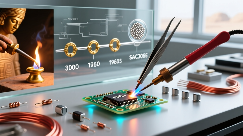
Metallurgical Evolution: From Leaded Rosin to SAC305
The physical materials used in IPC Class 3 soldering have undergone a radical transformation, driven by both environmental legislation and the physical limits of legacy alloys.
The Sn60/Pb40 and Sn63/Pb37 Era
For decades, Tin-Lead (SnPb) was the undisputed king of high-reliability soldering. Eutectic Sn63/Pb37 melts at a sharp 183°C (361°F), eliminating the plastic (pasty) phase where micro-cracks form if the joint is disturbed during cooling. Its predictable grain structure and excellent wetting characteristics made it the default for early IPC Class 3 and MIL-STD assemblies.
The RoHS Directive and the Rise of SAC305
The introduction of the EU's Restriction of Hazardous Substances (RoHS) directive in 2006 forced a massive industry pivot. The industry settled on SAC305 (96.5% Tin, 3.0% Silver, 0.5% Copper) as the lead-free standard. However, this created a massive headache for Class 3 manufacturers:
- Higher Melting Points: SAC305 melts at 217°C–220°C, requiring higher reflow and hand-soldering temperatures, which risks delaminating PCBs and damaging sensitive silicon.
- Tin Whiskers: Lead-free, high-tin alloys are susceptible to spontaneous tin whisker growth—microscopic conductive crystals that can cause short circuits in aerospace avionics years after deployment.
Because of these reliability risks, the Surface Mount Technology Association (SMTA) and various defense bodies secured exemptions for mission-critical Class 3 applications. Today, in 2026, while commercial Class 3 (like high-end server motherboards) uses SAC305 or specialized low-silver alloys like SAC405, aerospace and military Class 3 assemblies frequently still utilize Sn63/Pb37 to guarantee long-term reliability and prevent tin whisker catastrophes.
The Tooling Revolution: Meeting Class 3 Thermal Demands
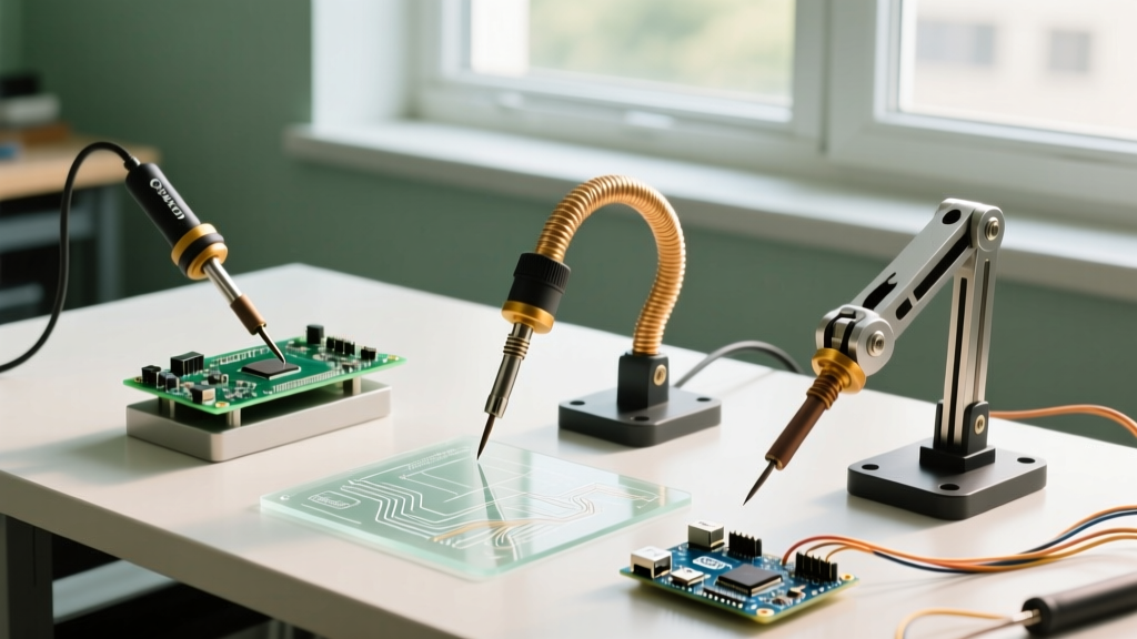
You cannot achieve IPC Class 3 perfection with a $25 hardware store soldering iron. As component densities increased and ground planes became more thermally massive, the tools required to solder them had to evolve from simple resistive heaters to intelligent, closed-loop thermal management systems.
From Dial-Control to Smart Thermal Profiling
Early soldering stations used basic rheostats or bimetallic thermostats. If an operator dragged the tip across a heavy copper ground plane, the tip temperature would plummet, resulting in a cold, grainy joint—an automatic Class 3 failure.
Modern Class 3 workstations utilize high-frequency induction or advanced digital closed-loop feedback. For example, the Metcal PS-900 uses SmartHeat® induction technology, where the tip itself is a ferromagnetic core that stops heating exactly at its Curie point (e.g., 350°C), providing massive thermal recovery without risking component overheating. Similarly, JBC's CD-2BQE stations utilize a proprietary cartridge system where the heating element is integrated directly into the tip, reducing thermal resistance to near-zero and allowing operators to solder heavy multi-layer PCBs and microscopic 0201 components on the same bench.
Flux Chemistry and the Cleanliness Mandate
IPC J-STD-001 places immense scrutiny on ionic cleanliness. Early highly-activated rosin (RA) fluxes were corrosive and required harsh CFC solvents to clean. The evolution of flux chemistry introduced ROL0 (Rosin, Low activity, 0% halides) and No-Clean formulations. However, for Class 3, "no-clean" is often a misnomer. In high-impedance medical devices or high-voltage aerospace systems, any flux residue can cause electrochemical migration (dendritic growth). Therefore, modern Class 3 protocols frequently mandate the use of water-soluble (OA) fluxes followed by rigorous ultrasonic or vapor-phase cleaning, verified by Ion Chromatography or ROSE (Resistivity of Solvent Extract) testing.
Inspection: Moving Beyond the 10x Loupe
Historically, Class 3 inspection relied on the trained human eye aided by a 10x magnification loupe and ring lighting. Inspectors would manually verify fillet shapes, wetting angles, and the absence of solder balls.
The advent of Ball Grid Arrays (BGAs), Bottom Termination Components (BTCs), and micro-vias rendered visual inspection obsolete for hidden joints. The evolution of Class 3 quality assurance now relies heavily on:
- 3D Solder Paste Inspection (SPI): Using structured light to measure paste volume and alignment before a single component is placed, preventing 70% of potential end-of-line defects.
- Automated Optical Inspection (AOI): High-resolution multi-spectral cameras that compare assembled boards against CAD golden samples to detect tombstoning, bridging, and insufficient wetting.
- 3D X-Ray (AXI): Essential for verifying the internal barrel fill of Plated Through-Holes (PTH) and detecting micro-voiding inside BGA spheres, which are critical failure points in high-vibration environments.
Setting Up a Class 3 Compliant Bench in 2026
For engineering firms, university labs, or advanced DIYers looking to prototype high-reliability hardware, building an IPC Class 3 compliant workstation requires a specific investment in precision tooling. Here is a practical, modern buyer's framework for a 2026 Class 3 bench setup:
- Primary Soldering Station: JBC CD-2BQE or Weller WX2021. Expected Cost: $700 - $950. These provide the sub-second thermal recovery required for heavy ground planes without exceeding the thermal mass limits of delicate SMD pads.
- Micro-Soldering / Rework: JBC Nanotweezers or a precision hot-air station like the Quick 861DW (with customized low-flow nozzles). Expected Cost: $400 - $600.
- Fume Extraction: BOFA AD Oracle 3 or Hakko FA-400. Class 3 environments mandate strict air quality control to prevent flux particulates from settling on adjacent high-impedance circuits. Expected Cost: $300 - $1,200.
- ESD & Thermal Management: A fully grounded, dissipative silicone mat (surface resistance of 10^6 to 10^9 ohms) and continuous wrist-strap monitoring. Expected Cost: $150.
- Magnification: Amscope or Vision Engineering trinocular stereo microscope with a 0.5x Barlow lens and ring LED. Expected Cost: $500 - $1,500.
The Future of High-Reliability Soldering
As we move deeper into the 2020s, the boundaries of IPC Class 3 are being pushed by the rise of flexible-hybrid electronics (FHE) and high-temperature automotive SiC (Silicon Carbide) power modules. The fundamental philosophy of IPC Class 3—documented, repeatable, and verifiable perfection—remains unchanged since its MIL-STD origins. However, the methods have evolved from the soldering iron and the loupe to closed-loop thermal cartridges and 3D X-ray tomography. Whether you are repairing a commercial drone or designing a CubeSat, respecting the history and strict methodology of Class 3 is the only way to ensure your electronics survive when failure is not an option.