
Defining the Solderer: Beyond the Tool and the Technician
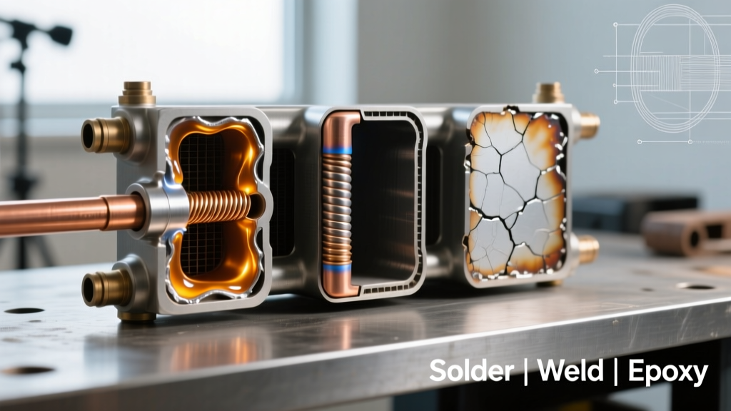
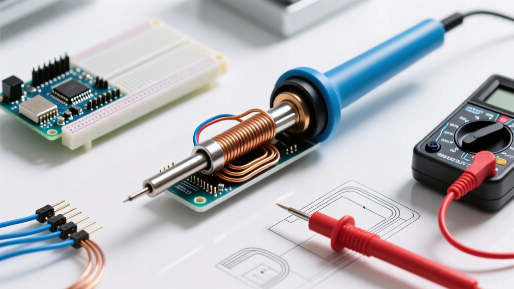
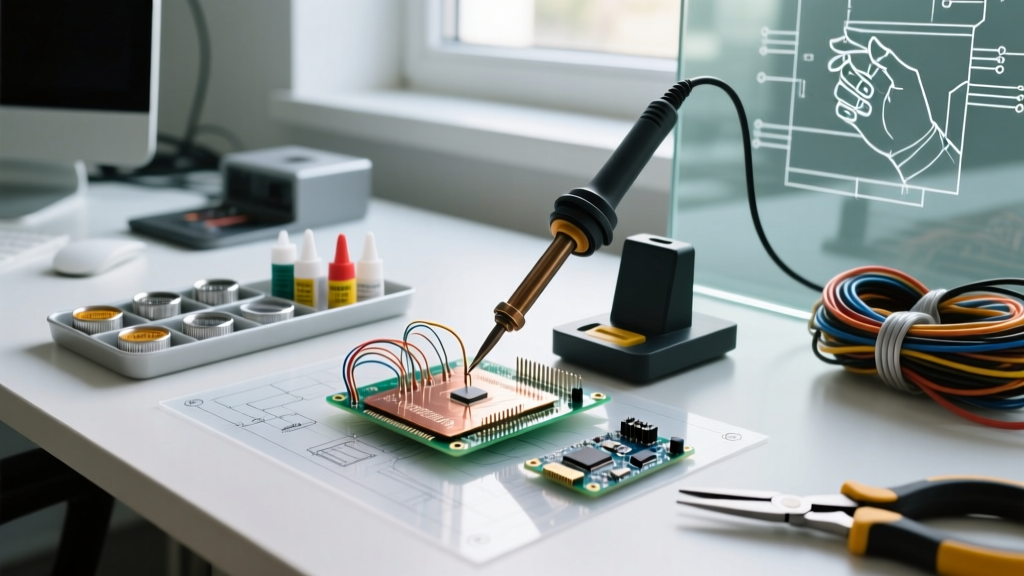
When an apprentice, hobbyist, or procurement manager asks, "what is a solderer," the literal answer is usually either the technician performing the work or the handheld thermal tool itself. However, in advanced electronics manufacturing, aerospace engineering, and metallurgical science, a solderer is defined as a closed-loop thermodynamic system. This system comprises the operator, the thermal delivery unit (the station and tip), the flux chemistry, and the base metallurgy. Understanding what a solderer truly is requires shifting focus from the physical iron to the complex interplay of heat transfer, oxide reduction, and Intermetallic Compound (IMC) formation.
In 2026, with the industry heavily reliant on lead-free SAC (Tin-Silver-Copper) alloys and high-density multi-layer PCBs, treating a solderer as merely a "hot stick" guarantees catastrophic failure modes like cold joints, pad lift-off, and tip dissolution. According to the IPC J-STD-001 standard, achieving a reliable solder joint requires precise control over thermal mass and wetting time. This guide deconstructs the solderer as a material compatibility system, providing a definitive matrix for matching thermal profiles to specific metals.
The Material Compatibility Matrix
Different base metals present unique oxidation barriers and thermal conductivity profiles. A solderer must adapt their equipment and chemistry to match the substrate. Below is the definitive compatibility matrix for common and exotic materials encountered in modern fabrication.
| Base Material | Oxide Layer Tenacity | Required Flux Chemistry | Thermal Mass & Recovery Need | Recommended Alloy & Temp Profile |
|---|---|---|---|---|
| Copper (FR4 PCB) | Low | Rosin (RMA) / No-Clean | Standard (60W-90W) | SAC305 @ 350°C or Sn63Pb37 @ 320°C |
| Aluminum (Heat Sinks) | Extreme (Instant reform) | Specialized Fluoride / Ultrasonic | High (130W+ Cartridge) | Indium-based or Sn-Zn @ 300-400°C |
| Stainless Steel | High | Aggressive Acid / Active Rosin | Medium-High (90W+) | Sn-Ag or Sn-Pb (with acid) @ 380°C |
| Kovar / Nickel (Aerospace) | Moderate-High | Active Acid / Specialized | Medium (70W-100W) | Sn-Ag-Cu @ 360°C |
| Brass / Bronze | Low-Moderate | Standard Rosin / Mild Acid | Standard (60W) | Sn-Pb or Lead-Free @ 330°C |
Deep Dive: Metallurgical Edge Cases and Failure Modes
Aluminum and the Oxide Barrier
Aluminum is notorious in the soldering world because its oxide layer (Al2O3) reforms in milliseconds when exposed to oxygen, even in the presence of molten solder. Standard rosin fluxes are entirely ineffective here. To successfully solder aluminum, the solderer must employ either mechanical disruption (such as ultrasonic soldering irons that use high-frequency vibrations to shatter the oxide layer) or highly aggressive fluoride-based fluxes. Furthermore, aluminum acts as a massive heat sink. Using a standard 40W iron will result in a cold, pasty joint. A high-thermal-mass system, such as a JBC T245 handle with a C245 heavy-chisel cartridge, is mandatory to push past the 300°C threshold without stalling the thermal recovery.
Stainless Steel and Nickel Alloys
Stainless steel relies on a chromium oxide layer for its corrosion resistance. This same layer prevents solder wetting. To solder stainless steel, the solderer must utilize an aggressive organic acid (OA) or inorganic acid flux to etch the surface. Warning: Acid fluxes are highly corrosive and must never be used on PCBs or electronic components, as the residual ions will cause electrochemical migration (dendritic growth) and short circuits. These fluxes are strictly for mechanical, plumbing, or structural joints, requiring immediate post-solder neutralization and cleaning.
The IMC Layer: Where the Magic (and Failure) Happens
A solder joint is not merely glue; it is a metallurgical bond. When molten tin contacts copper, they react to form an Intermetallic Compound (IMC) layer, typically Cu6Sn5 and Cu3Sn. According to metallurgical research cited by Indium Corporation, the ideal IMC layer thickness is between 1 to 3 micrometers. If the solderer applies excessive heat or dwells too long, the IMC layer grows too thick and becomes brittle, leading to micro-cracking under thermal cycling or mechanical shock. This is why precise thermal control is the hallmark of a professional soldering system.
Thermal Recovery and Tip Geometry Selection
The physical shape of the soldering tip dictates the surface area contact and the rate of thermal transfer. Understanding what a solderer is requires understanding how tip geometry interacts with material mass.
- Micro-Pencil (e.g., JBC C115-101): Ideal for 0201 SMD components and fine-pitch QFNs. Low thermal mass, high precision. Requires a station with ultra-fast response times to prevent localized overheating.
- Standard Chisel (e.g., Hakko T18-D24): The workhorse for through-hole components and standard SOIC ICs. Provides a balance of surface area and maneuverability.
- Heavy Bevel / Spoon (e.g., Metcal STV-CH50): Designed for high-mass applications like soldering thick gauge wires (12 AWG or larger) to large ground planes. The concave shape holds a pool of molten solder, maximizing thermal transfer via convection rather than just conduction.
Expert Insight: When soldering to a multi-layer PCB with heavy internal copper pours (e.g., a 6-layer FR4 board with 2oz copper ground planes), the board acts as a massive heat sink. A standard 70W station will stall, dropping the tip temperature below the alloy's liquidus point. In 2026, professionals rely on RF induction systems (like Metcal) or smart-cartridge systems (like JBC) that detect the thermal load and instantly dump up to 130W of power into the tip to maintain the setpoint.
Flux Chemistry: The True Bridge Between Metals
Flux is arguably more important than the solder alloy itself. It is the chemical agent that removes oxidation and prevents re-oxidation during the heating phase.
- Rosin (R, RMA, RA): Derived from pine sap. RMA (Rosin Mildly Activated) is the standard for commercial electronics. It is non-corrosive at room temperature and safe to leave on most PCBs.
- No-Clean (NC): Formulated with synthetic resins. Leaves a minimal, clear residue that is designed to be left on the board. However, if subjected to high-temperature reflow profiles, the residue can carbonize and become slightly conductive or corrosive.
- Water-Soluble (OA): Highly active organic acids. Provides brilliant wetting on slightly oxidized boards but must be cleaned with deionized water immediately after soldering to prevent catastrophic corrosion.
- Inorganic Acid (IA): Used for plumbing, roofing, and structural steel. Never use on electronics.
Edge Case: Iron Dissolution and Tip Death
One of the most expensive mistakes a novice makes is leaving a lead-free SAC305 alloy melting on a tip at 380°C. Tin is highly aggressive and will literally leach the iron plating off the copper core of the soldering tip—a process known as iron dissolution. Once the iron plating is breached, the molten solder dissolves the copper core, pitting the tip and ruining its thermal transfer capabilities. To combat this, modern solderers use tips with specialized multi-layer platings (iron, nickel, chromium) and strictly adhere to the 350°C maximum threshold for lead-free alloys, utilizing standby/sleep modes to drop the temperature to 150°C when not actively soldering.
Step-by-Step Framework for Unknown Metals
When tasked with joining an unidentified alloy, follow this systematic framework to determine material compatibility:
- Magnetic Test: Use a magnet. If it sticks, you are likely dealing with steel or iron, requiring acid flux and high heat. If it does not stick, proceed to step 2.
- Scratch Test: Scratch the surface. Aluminum is soft and leaves a grey mark; stainless steel is hard; brass is yellowish and softer.
- Flux Escalation: Start with a mild RMA rosin flux. If the solder beads up and refuses to wet (forming a high contact angle), clean the area and step up to an active organic acid flux.
- Thermal Escalation: If the solder freezes instantly upon touching the metal, your thermal mass is insufficient. Switch to a larger bevel tip and increase the station wattage or temperature by 20°C increments, never exceeding the maximum rating of your flux.
Conclusion
So, what is a solderer? It is a master of thermodynamics, chemistry, and metallurgy. Whether you are assembling a delicate IoT sensor using a micro-pencil tip and no-clean flux, or brazing a heavy-gauge copper busbar for an EV battery pack, success relies on matching the thermal profile and chemical activators to the base material. By respecting the oxide layers, managing the IMC growth, and utilizing modern thermal recovery stations, you elevate the act of soldering from a simple craft to a precise, repeatable engineering discipline. For further reading on aerospace and high-reliability soldering workmanship, consult the NASA Electronic Parts and Packaging (NEPP) Program guidelines, which remain the gold standard for mission-critical material compatibility.