
The Reality of Industrial Motherboard Soldering
When technicians discuss motherboard soldering, the conversation often defaults to consumer electronics or simple through-hole repairs. However, industrial motherboard soldering—specifically for data center server boards, telecommunications backplanes, and aerospace computing modules—operates under an entirely different set of physical and regulatory constraints. Modern enterprise boards, such as those housing AMD EPYC or Intel Xeon Scalable processors, feature 12 to 16-layer PCBs with heavy 2oz to 4oz copper ground planes. These massive thermal sinks make traditional soldering methods obsolete and demand precision BGA (Ball Grid Array) rework protocols.
In 2026, the shift toward PCIe 6.0 architectures and DDR5 high-speed routing means that solder joint impedance and structural integrity are more critical than ever. A single micro-fracture in a BGA solder sphere can cause intermittent signal degradation, leading to catastrophic data center downtime. This guide explores the advanced equipment, thermal profiles, and IPC Class 3 standards required for professional industrial motherboard soldering.
Thermal Dynamics: Overcoming the Ground Plane Heat Sink
The primary adversary in server board repair is thermal dissipation. When a soldering iron tip contacts a via connected to an internal ground plane, the copper acts as a massive heat sink, pulling thermal energy away from the tip. A standard 65W soldering station will experience immediate thermal dropout, resulting in cold solder joints or, worse, prolonged dwell times that delaminate the PCB substrate.
The Preheating Mandate
To mitigate thermal shock and reduce the delta-T (temperature differential) between the iron tip and the solder joint, bottom preheating is non-negotiable. Industrial repair facilities utilize IR (Infrared) or quartz-element preheaters to bring the entire motherboard to a baseline temperature of 120°C to 140°C. This achieves two critical outcomes:
- Reduces Required Tip Temperature: By preheating the board, the soldering iron only needs to supply the remaining 80°C to 100°C to reach the liquidus state of SAC305 solder (217°C), preserving the flux chemistry and preventing pad lifting.
- Prevents PCB Warpage: Even, controlled bottom heating prevents the localized thermal expansion that causes multi-layer boards to warp or twist during localized top-side heating.
BGA Rework Stations: 2026 Equipment Comparison
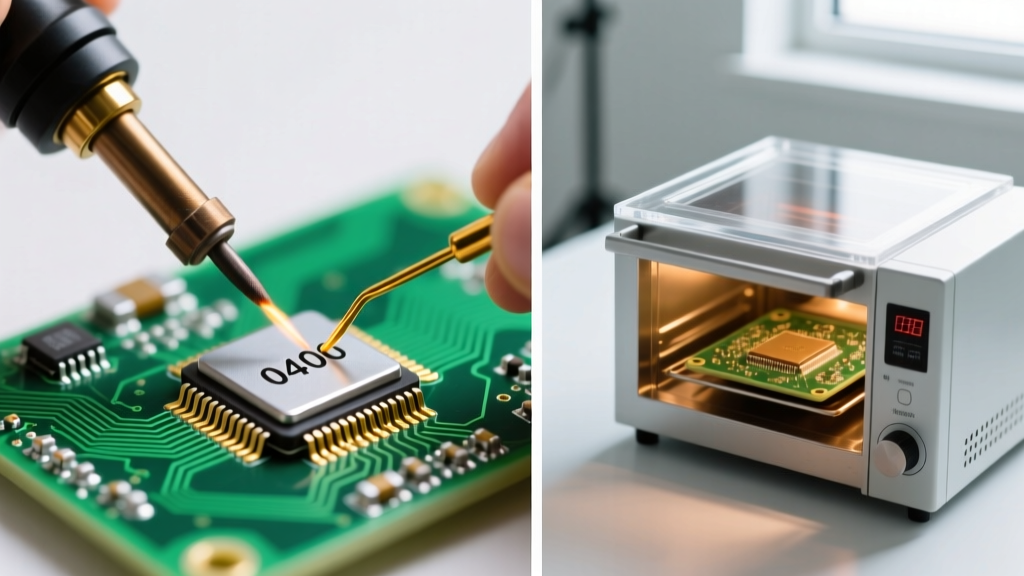
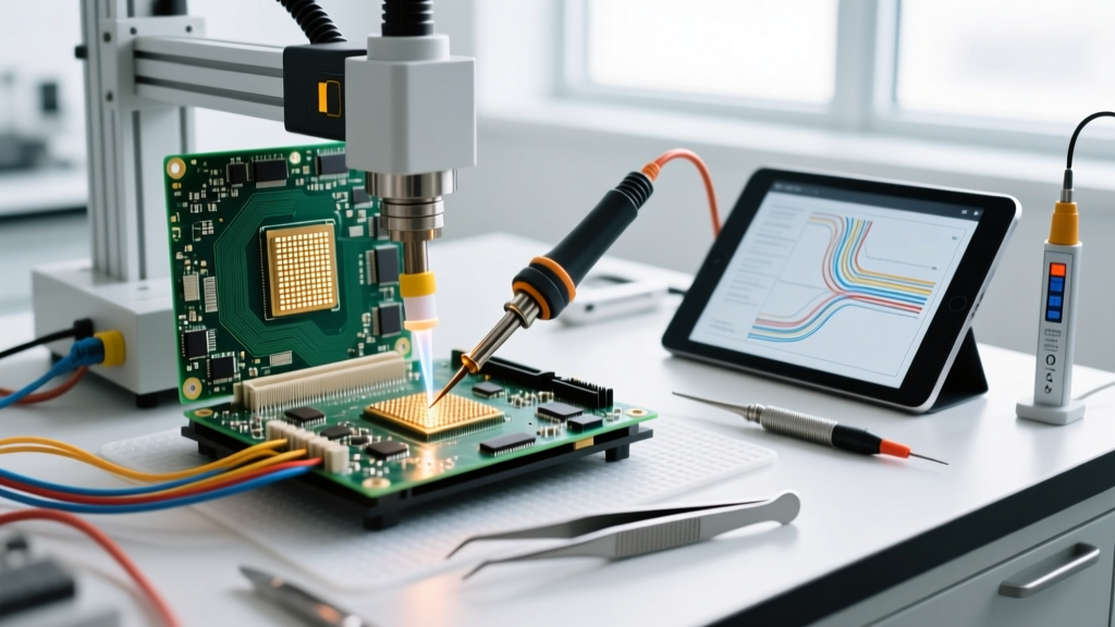
For replacing PCH (Platform Controller Hub) chips, network controllers, or CPU sockets, a precision BGA rework station is required. These machines utilize closed-loop thermocouple feedback to execute multi-stage thermal profiles. Below is a comparison of the industry-standard BGA rework systems used in professional motherboard soldering environments.
| Equipment Model | Approx. Price (USD) | Preheat Power | Temp Accuracy | Best Industry Application |
|---|---|---|---|---|
| Quick 862DW | $680 - $750 | 800W (IR) | ± 2°C | Mid-tier repair shops, standard ATX server boards |
| Zhuomao ZM-T7A | $1,200 - $1,400 | 1200W (IR) | ± 1°C | Automated optical alignment, high-volume SMD/BGA |
| Weller WRS-3000 | $4,500 - $4,800 | 1600W (Quartz) | ± 0.5°C | Aerospace, IPC Class 3 data center compliance |
For facilities strictly adhering to IPC-A-610 Class 3 standards for high-performance electronic assemblies, the Weller WRS-3000 is the benchmark. Its closed-loop airflow and precise Z-axis placement ensure that BGA voiding remains below the strict 25% threshold required for mission-critical hardware.
Flux Chemistry and Solder Alloy Selection
Industrial motherboard soldering strictly utilizes lead-free alloys, predominantly SAC305 (Sn96.5/Ag3.0/Cu0.5). SAC305 has a melting point of 217°C, requiring peak reflow temperatures of 240°C to 245°C. The choice of flux is equally critical, particularly for BGA reballing and micro-SMD rework.
Tacky Flux vs. Liquid Flux
For BGA reballing, technicians rely on high-tack, no-clean fluxes like Amtech NC-559-V2-TF or Indium Corporation's TACFlux 020B. These fluxes serve a dual purpose: they provide the necessary surface tension to hold the BGA chip in place during the reflow profile, and they contain advanced activators that clean oxidized pads without leaving corrosive residues. According to technical resources from Indium Corporation, using halide-free, no-clean fluxes is essential for preventing electrochemical migration (dendrite growth) in high-humidity server environments.
Step-by-Step BGA Rework Flow for Server Boards
Executing a successful BGA replacement on a 14-layer motherboard requires a methodical approach. The following profile is optimized for a 25x25mm PCH chip using a standard IR rework station:
- Stage 1: Preheat & Soak (0 - 120 seconds)
Bottom IR set to 130°C. Top hot air ramps from 100°C to 150°C. This gently activates the flux and equalizes board temperature. - Stage 2: Ramp to Reflow (120 - 180 seconds)
Top air increases to 220°C. The solder paste approaches its liquidus state. Airflow must be reduced to 20% to prevent displacing adjacent 0402 passives. - Stage 3: Peak Reflow (180 - 210 seconds)
Top air peaks at 245°C. The solder spheres melt and wet the PCB pads. The vacuum pickup nozzle engages to remove the defective chip. - Stage 4: Site Dressing
Using a Hakko FX-951 with a flat bevel tip (T12-D52) and high-quality desoldering braid (e.g., Chemtronics Soder-Wick), the technician removes residual solder. The site is cleaned with 99% isopropyl alcohol and inspected under a 40x stereo microscope. - Stage 5: Placement and Final Reflow
The re-balled chip is aligned using the station's optical split-vision system and the reflow profile is repeated to permanently seat the component.
Expert Insight: Underfill Removal
Many enterprise network controllers and ASICs are secured with black epoxy underfill. Never attempt to pry these chips cold. Apply localized heat (200°C) with a micro-hot air pencil to soften the underfill, then use a specialized tungsten carbide scraper to gently slice through the epoxy matrix without severing the microscopic PCB traces beneath.
Micro-SMD Rework: The 0201 and 01005 Challenge
Modern server motherboards are densely packed with decoupling capacitors and pull-up resistors in 0201 (0.6mm x 0.3mm) and even 01005 imperial footprints. Reworking these components near large BGA chips requires specialized micro-soldering techniques. Technicians utilize micro-pencil irons with 0.2mm tips, paired with high-magnification digital microscopes. As outlined in the Hakko E-Learning Portal, maintaining a tip temperature of 320°C to 340°C with a rapid thermal recovery tip (like the T12 series) is vital to prevent tombstoning—a defect where surface tension pulls one end of the capacitor off the pad due to uneven heating.
Common Failure Modes in Industrial Repairs
Understanding failure modes is critical for quality assurance in motherboard soldering. The most frequent defects encountered in server board rework include:
- Pad Cratering: Caused by mechanical stress during chip removal before the solder has fully liquefied, or by excessive localized heat degrading the FR-4 resin's glass transition temperature (Tg).
- Solder Bridging: Occurs when flux activity is exhausted before reflow is complete, or when the Z-axis placement height is too low, squeezing molten solder between adjacent pads.
- Head-in-Pillow (HiP) Defect: A notorious BGA failure where the solder ball on the component melts and re-solidifies without properly wetting the solder paste on the PCB pad, resulting in a mechanically weak, non-conductive joint.
Conclusion: The ROI of In-House Motherboard Soldering
For data center operators and industrial repair facilities, mastering advanced motherboard soldering yields a massive return on investment. Replacing a single defective $4,000 server motherboard via OEM RMA can take weeks and incur high shipping costs. By investing in a precision BGA rework station, mastering IPC-compliant thermal profiles, and utilizing premium flux chemistries, technicians can restore mission-critical hardware in-house within hours, ensuring maximum uptime and operational efficiency.