
Defining High Temperature Soldering in Modern Electronics
When engineers and technicians discuss high temperature soldering, they are rarely talking about simply turning a dial to the maximum setting. In professional electronics manufacturing and advanced DIY prototyping, high temperature soldering refers to processes utilizing alloys with a liquidus (melting) point above 250°C (482°F), or processes that require soldering iron tip temperatures exceeding 400°C (752°F) to overcome massive thermal mass challenges. The evolution of these techniques is a fascinating journey driven by aerospace demands, environmental regulations, and the relentless miniaturization of high-power components.
Today, whether you are attaching a heavy copper ground plane to an RF amplifier chassis or hermetically sealing a photonics package, understanding the historical context and modern realities of high-temperature alloys and equipment is critical for achieving reliable, IPC-compliant joints.
The Pre-RoHS Era: Step Soldering and High-Lead Alloys
Before the mid-2000s, high temperature soldering was largely synonymous with high-lead (Pb) alloys. In military and aerospace applications, engineers frequently utilized a technique known as step soldering. This involved using a high-temperature alloy like Sn5/Pb95 (melting point 308°C–312°C) for the first set of joints, followed by a lower-temperature alloy like Sn63/Pb37 (melting point 183°C) for subsequent components.
This evolutionary step allowed technicians to secure heavy, high-thermal-mass components—such as power transistors and large transformers—without risking the re-melting of previously established connections. According to historical workmanship guidelines maintained by the NASA Electronic Parts and Packaging (NEPP) Program, high-lead solders were prized not just for their thermal hierarchy, but for their exceptional resistance to thermal fatigue and creep in extreme environments.
Historical Insight: Early high-temperature soldering irons were primarily resistive, relying on massive, slow-recovering ceramic heating elements. Technicians often had to pre-heat entire PCB assemblies on hotplates to 100°C just to prevent the iron tip from stalling out when touching a heavy ground plane.
The RoHS Catalyst: How Lead-Free Forced Temperatures Higher
The paradigm shifted dramatically with the implementation of the Restriction of Hazardous Substances (RoHS) directive in 2006. The industry standard shifted to SAC (Tin-Silver-Copper) alloys, primarily SAC305 (Sn96.5/Ag3.0/Cu0.5). While SAC305 has a liquidus of roughly 217°C–220°C—lower than high-lead solders—it exhibits notoriously poor wetting characteristics and a sluggish flow profile compared to eutectic tin-lead.
To achieve proper metallurgical wetting and intermetallic compound (IMC) formation with SAC alloys, the thermal delta between the melting point and the application temperature had to increase. Soldering iron tips that previously operated comfortably at 315°C for leaded work suddenly needed to be pushed to 360°C–380°C to transfer enough instantaneous heat to melt the SAC paste and activate the no-clean fluxes. This regulatory shift inadvertently birthed the modern high-temperature hand-soldering equipment market.
The Equipment Evolution: From Resistive to Inductive and Cartridge
The demand for higher process temperatures without destroying delicate PCB pads forced a revolution in soldering station architecture. The historical 50-watt resistive irons were entirely inadequate for high-temp RoHS work on multi-layer boards.
1. Inductive Heating (SmartHeat)
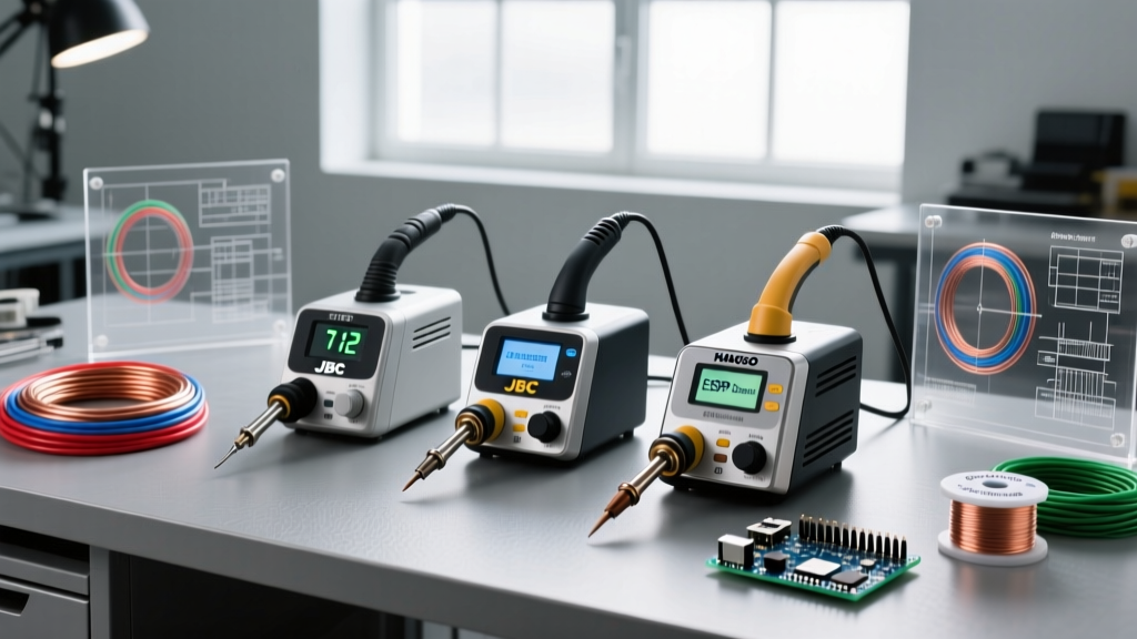
Pioneered by Metcal, inductive heating uses radio frequency (RF) fields to heat the tip directly via eddy currents. The temperature is governed by the Curie point of the ferromagnetic alloy in the tip. For high-temperature applications, technicians use specialized tips (such as the Metcal 700 or 800 series) designed to hold a precise 390°C or 440°C without overshooting. A modern station like the Metcal CV-5200 (retailing around $950–$1,100) provides massive instantaneous thermal recovery, preventing the tip temperature from dropping when it contacts a high-mass joint.
2. Direct-Drive Cartridge Systems
Brands like JBC revolutionized the market by placing the ceramic heating element directly inside the tip cartridge, mere millimeters from the working edge. The JBC CD-2BE station (approximately $650–$750) can drive heavy-duty C470 series tips to 420°C and recover from a thermal drop in under two seconds. This localized high-heat transfer minimizes the time the PCB pad is exposed to extreme temperatures, reducing the risk of delamination.
3. Laser and Hot Gas Reflow
For ultra-high-temperature exotic alloys, hand irons are abandoned entirely. Automated laser soldering systems (often costing $15,000 to $50,000+) use diode lasers to deliver pinpoint thermal energy, while precision hot-gas rework stations use nitrogen-heated airflow to profile complex thermal curves without oxidizing the joint.
Modern Exotic High-Temperature Alloys
Beyond standard SAC, advanced sectors rely on specialized high-temperature alloys. Sourcing these requires specialized suppliers like Indium Corporation, which engineers alloys for extreme thermal and mechanical stress.
| Alloy Designation | Composition | Solidus / Liquidus | Typical Process Temp | Primary Application |
|---|---|---|---|---|
| Sn5/Pb95 | 5% Sn, 95% Pb | 308°C / 312°C | 350°C - 380°C | Aerospace step-soldering, high-temp die attach (Exempt from RoHS in specific mil/aero apps) |
| SAC305 | 96.5% Sn, 3% Ag, 0.5% Cu | 217°C / 220°C | 350°C - 380°C | Standard RoHS commercial electronics, heavy ground plane attachments |
| Au80/Sn20 | 80% Au, 20% Sn | 278°C / 278°C | 300°C - 320°C | Photonics, laser diode packaging, hermetic sealing, medical implants |
| Sn10/Sb90 | 10% Sn, 90% Sb | 240°C / 370°C | 400°C+ | High-temperature semiconductor die attach, acoustic transducers |
PCB Material Limits and Thermal Edge Cases
A critical failure mode in high temperature soldering is ignoring the glass transition temperature (Tg) of the PCB substrate. Standard FR-4 has a Tg of roughly 130°C–140°C. High-Tg FR-4 pushes this to 170°C. When applying a 400°C iron tip, the localized temperature can easily exceed the decomposition temperature (Td) of the resin, which is typically around 300°C–320°C for standard materials.
Troubleshooting Thermal Damage
- Pad Lift and Delamination: If the Z-axis expansion of the PCB resin exceeds the tensile strength of the copper plating, the barrel will crack or the pad will lift. Solution: Use high-thermal-conductivity tips (like chisel or bevel shapes) to minimize dwell time to under 3 seconds per joint.
- Flux Burn-Off: At temperatures above 380°C, standard rosin-based (ROL0) fluxes boil off and carbonize before the solder can wet the pad, leaving a black, non-conductive residue that prevents IMC formation. Solution: Switch to high-solids, high-temperature activated fluxes, or use a localized nitrogen shroud to prevent oxidation and extend flux life.
- Component Degradation: Many plastic-bodied connectors and SMD electrolytic capacitors will melt or vent at sustained temperatures above 260°C. Solution: Utilize Kapton (polyimide) thermal barrier tape and aluminum heat-sink clips to protect adjacent components during high-temp operations.
Industry Standards and Compliance
Any high-temperature soldering process in a professional environment must adhere to strict industry guidelines. The IPC standards body outlines acceptable thermal excursion limits and workmanship criteria in documents like IPC J-STD-001 and IPC-A-610. These standards dictate that while high temperatures are sometimes necessary, the resulting joint must not exhibit thermal degradation, scorched flux residues, or damaged laminate. Inspectors will specifically look for charring of the solder mask or blistering of the conformal coating as immediate indicators of improper high-temperature technique.
Conclusion: The Future of High-Heat Joining
The evolution of high temperature soldering is a testament to the electronics industry's ability to adapt to physical and regulatory constraints. From the heavy, lead-laden step-soldering of the Apollo era to the precise, inductive-driven SAC and Gold-Tin processes of 2026, the core challenge remains the same: delivering massive thermal energy to a microscopic area without destroying the surrounding architecture. For the modern DIY enthusiast and professional engineer alike, investing in advanced cartridge or inductive equipment, understanding the exact metallurgical properties of exotic alloys, and respecting the thermal limits of PCB substrates are the keys to mastering high-temperature electronics assembly.