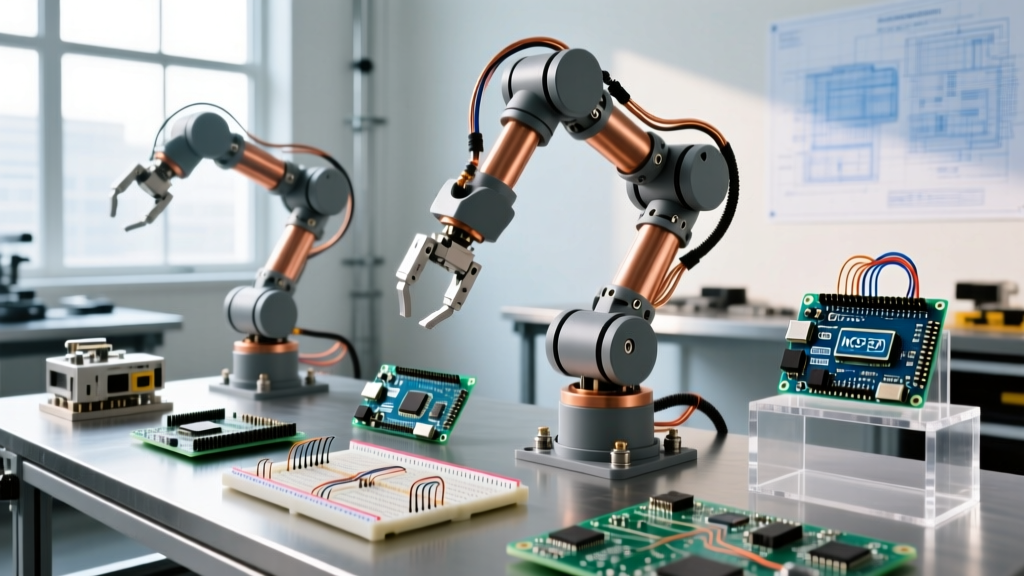

The 2026 Community Showcase: Elevating Arduino Robot Arms
Over the past decade, arduino robot arms have transitioned from simple educational toys to highly capable desktop automation tools. In our 2026 ElectricalFlux Community Project Showcase, we reviewed dozens of submissions from makers, engineers, and students. The goal? To identify which builds offer the best blend of mechanical rigidity, electronic reliability, and software flexibility.
Whether you are assembling a commercial kit or designing a custom 3D-printed manipulator, the core challenges remain the same: managing transient current spikes, eliminating servo jitter, and calculating inverse kinematics. Below, we highlight three standout community projects that tackle these issues head-on, followed by a deep dive into the power and communication architectures that make them work.
Community Build #1: The Freenove Ultimate PCA9685 Arm
The most popular entry-level submission in our showcase was based on the Freenove Robot Arm Kit. While the mechanical acrylic and metal-gear servo design is standard, the community's approach to the control architecture sets this build apart.
Technical Highlights
- Actuators: 4x TowerPro MG996R (13 kg-cm torque, metal gears).
- Driver: PCA9685 16-Channel PWM Driver (I2C address
0x40). - Brain: Arduino Uno R3 (upgraded by the community to the Uno R4 WiFi for native MQTT telemetry).
Our community members noted that the stock Freenove power supply (a basic 5V 4A wall adapter) is insufficient for simultaneous multi-joint movement. When all four MG996R servos stall or start under load, they can draw up to 2.5A each. The community consensus mandates upgrading to a 5V 10A (50W) switching power supply to prevent brownouts and Arduino resets.
Community Insight: 'If your Arduino resets every time the base servo rotates, you are experiencing a voltage drop on the 5V rail. Never power high-torque servos directly from the Arduino's onboard 5V pin.'
Community Build #2: OSOYOO Robotic Arm Edge (Stacking Shield Approach)
For makers who prefer shield-stacking over breadboard wiring, the OSOYOO Robotic Arm Edge remains a staple. This kit uses a custom motor control shield that sits directly atop the Arduino Mega 2560.
Why the Mega 2560?
Unlike simpler arms, the OSOYOO Edge features 5 degrees of freedom (DoF) plus a gripper. The Arduino Mega provides the necessary hardware serial ports and I/O pins to handle the shield, an ultrasonic sensor for collision avoidance, and a joystick module simultaneously without relying on software serial multiplexing.
However, our community testers identified a specific edge case: I2C bus capacitance. When users add an OLED display to the same I2C bus as the motor shield, signal degradation causes intermittent communication failures. The fix? Adding 4.7kΩ pull-up resistors to the SDA and SCL lines, a crucial step often omitted in the official Arduino I2C Communication Guide.
Community Build #3: Custom NEMA 17 & Arduino Uno R4 WiFi
The most advanced showcase entry bypassed standard hobby servos entirely. Built by a university robotics club, this custom arm utilizes 3D-printed PETG joints driven by NEMA 17 stepper motors and planetary gearboxes (50:1 ratio).
Stepper vs. Servo Architecture
Stepper motors provide superior holding torque and repeatability, essential for precision tasks like PCB soldering or liquid handling. The control architecture uses the Arduino Uno R4 WiFi communicating via UART to three TB6600 stepper drivers.
- Microstepping: Set to 1/16 for smooth trajectory interpolation.
- Power: 24V 15A Mean Well LRS-350-24 PSU.
- Kinematics: Custom C++ implementation of Denavit-Hartenberg (DH) parameters running on the R4's 48MHz ARM Cortex-M4 processor.
By leveraging the Uno R4's 14-bit DAC and increased processing speed, the team achieved fluid motion profiles (trapezoidal acceleration) that older 8-bit ATmega328P boards simply could not compute in real-time.
Showdown: 2026 Arduino Robot Arm Comparison Matrix
| Feature | Freenove Kit (Modified) | OSOYOO Edge | Custom NEMA 17 Build |
|---|---|---|---|
| Estimated Cost | $75 - $95 | $110 - $130 | $180 - $250 |
| Degrees of Freedom | 4 DoF + Gripper | 5 DoF + Gripper | 4 DoF (High Precision) |
| Actuator Type | MG996R DC Servos | MG90S / MG996R Mix | NEMA 17 Steppers |
| Repeatability | ± 2.0 mm | ± 1.5 mm | ± 0.1 mm |
| Best Use Case | Sorting, basic pick-and-place | Education, maze solving | Soldering, CNC plotting |
| Programming Skill | Beginner | Intermediate | Advanced (Kinematics) |
Deep Dive: Eliminating Servo Jitter and Power Failures
The most common failure mode reported in Hackaday robot arm projects and our own community forums is micro-jitter during idle states. This is rarely a software bug; it is almost always an electrical noise issue. Here is the definitive 2026 troubleshooting checklist for stabilizing your Arduino robot arms.
1. The Ground Loop Trap
If you are powering your Arduino via USB while simultaneously powering the servos via a bench supply, you must connect the grounds. However, connecting the USB ground directly to a noisy switching power supply ground can introduce high-frequency noise into the Arduino's ATmega/RA4M1 chip. Solution: Use a common ground point (star grounding topology) and place a 100µF decoupling capacitor across the Arduino's 5V and GND pins.
2. PWM Signal Degradation
When driving servos directly from the Arduino's digital pins using the standard Arduino Servo Library, the 50Hz PWM signal can suffer from timing interrupts if your code includes heavy serial printing or delay functions. Solution: Offload PWM generation to a dedicated hardware controller like the PCA9685 or Adafruit PWM Shield. These chips maintain rock-solid pulse widths via I2C, completely isolating the servos from Arduino CPU load spikes.
3. Transient Current Buffering
When an MG996R servo changes direction, it creates a massive inrush current. If your power supply cannot respond in microseconds, the voltage sags, causing the servo's internal potentiometer to misread its position, resulting in oscillation. Solution: Solder a 1000µF 16V electrolytic capacitor directly across the VCC and GND terminals of your servo driver board. This acts as a local energy reservoir, smoothing out transient spikes.
Software Architecture: Moving Beyond Basic Angles
Beginner kits rely on hard-coded joint angles (e.g., servo1.write(90)). However, real-world automation requires Cartesian coordinate control (X, Y, Z).
For 2026 builds, we highly recommend utilizing the FABRIK (Forward And Backward Reaching Inverse Kinematics) algorithm. Unlike complex analytical IK solutions that require heavy matrix math, FABRIK is an iterative, geometric approach that runs efficiently even on a standard Arduino Uno. It allows you to input a target XYZ coordinate, and the algorithm calculates the exact servo angles required to place the end-effector at that point.
Frequently Asked Questions (FAQ)
Can I power Arduino robot arms with a standard 9V battery?
No. Standard 9V alkaline batteries have a very high internal resistance and cannot deliver the 2+ Amps required by standard hobby servos. Attempting to do so will result in immediate voltage sag, erratic servo behavior, and potential damage to the battery. Always use a regulated 5V switching power supply (minimum 5A for a 4-servo arm).
Is the Arduino Uno R4 WiFi necessary for a robot arm?
Not strictly necessary for basic movements, but highly recommended for modern IoT integration. The R4 WiFi allows you to send telemetry data (joint temperatures, current draw) to a cloud dashboard via MQTT, and enables wireless control via a web interface without needing an external ESP32 module.
Why do my servos hum loudly when holding a position?
A continuous hum indicates the servo is constantly micro-adjusting to hold its position. This is usually caused by mechanical binding in the arm's joints, excessive payload beyond the servo's torque rating, or a noisy power supply causing the internal potentiometer to read fluctuating voltage levels. Check your mechanical tolerances and add bearing blocks to high-stress joints.


