
The Evolution of Beginner Arduino Projects in 2026
When enthusiasts first search for beginner arduino projects, they are often met with outdated tutorials relying on the legacy Arduino Uno R3 and bulky, unreliable Wi-Fi shields. In 2026, the landscape of home automation has fundamentally shifted. The modern standard for entry-level IoT is the Arduino Nano ESP32. By combining the familiar Arduino Nano footprint with a dual-core ESP32-S3 microcontroller, beginners can now build native, cloud-connected smart home devices without writing a single line of complex networking code.
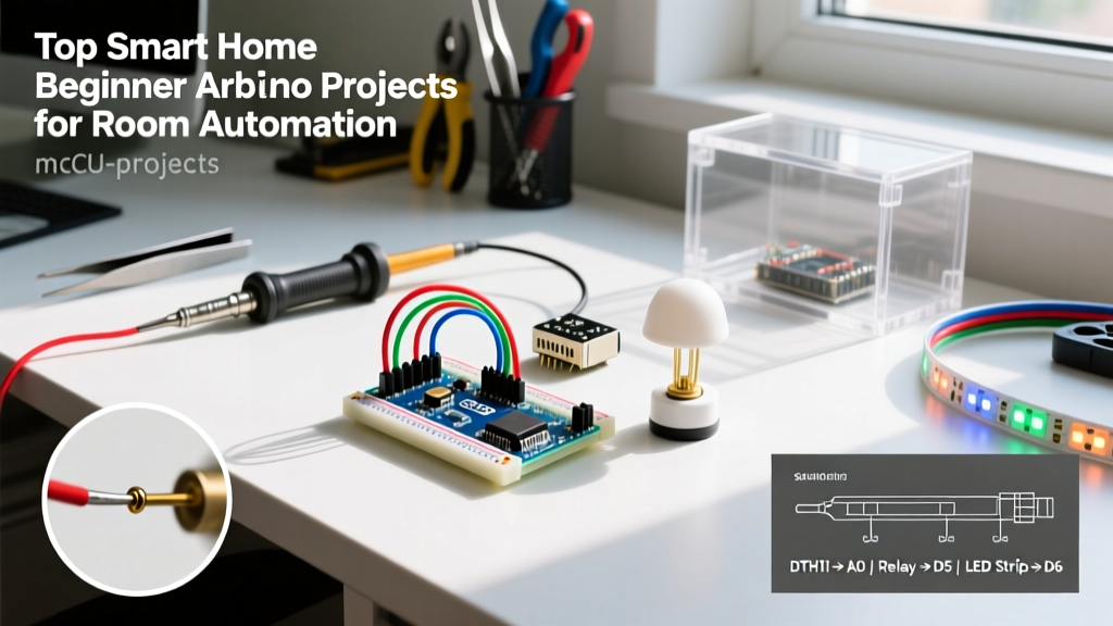
In this guide, we will walk through a highly practical, real-world home automation build: The Sentient Bedroom Controller. This project monitors ambient temperature and humidity, automatically triggering a USB desk fan when the room gets stuffy, and uses a PIR motion sensor to control accent lighting. It is the perfect bridge between basic blink-LED tutorials and advanced, whole-home IoT deployments.
Expert Insight: According to the U.S. Department of Energy, localized smart climate and lighting controls can reduce residential energy waste by up to 15% annually. Building your own localized sensor nodes ensures you aren't relying on cloud-dependent commercial hubs that may lose functionality if the manufacturer shuts down their servers.
Bill of Materials (BOM) & Cost Breakdown
Commercial smart home hubs and proprietary sensors can easily exceed $150. By sourcing standard maker components, you can build a more customizable node for a fraction of the cost. Below is the exact hardware list used for this build, with average 2026 pricing from reputable electronics distributors.
| Component | Model / Specification | Estimated Cost | Function |
|---|---|---|---|
| Microcontroller | Arduino Nano ESP32 (ABX00092) | $21.50 | Core logic, Wi-Fi/BLE, Cloud API |
| Env. Sensor | BME280 I2C Breakout (3.3V) | $5.50 | Temp, Humidity, Barometric Pressure |
| Motion Sensor | HC-SR501 PIR Module | $2.00 | Passive Infrared Occupancy Detection |
| Actuator | 5V 2-Channel Relay Module (Optocoupler) | $4.00 | Switching 120V/240V lamps or 5V USB fans |
| Power Supply | 5V 3A USB-C PD Wall Adapter | $6.00 | Reliable power for relays and ESP32 |
| Total | ~$39.00 |
Wiring Schematic & Pinout Guide
One of the most common failure points in beginner arduino projects is incorrect I2C addressing and voltage mismatching. The Arduino Nano ESP32 operates at 3.3V logic. While the BME280 is natively 3.3V, the HC-SR501 PIR sensor requires 5V to operate reliably and outputs a 3.3V HIGH signal, which is perfectly safe for the ESP32 GPIO pins.
1. BME280 Environmental Sensor (I2C)
- VCC: Connect to 3.3V pin on the Nano ESP32.
- GND: Connect to GND.
- SDA: Connect to A4 (Native I2C Data).
- SCL: Connect to A5 (Native I2C Clock).
Note: For a complete pin mapping reference, always consult the official Arduino Nano ESP32 Cheat Sheet to verify I2C bus assignments, as they differ from legacy ATmega328P boards.
2. HC-SR501 PIR Motion Sensor
- VCC: Connect to VIN (5V from USB-C).
- GND: Connect to GND.
- OUT: Connect to Digital Pin D2.
3. 2-Channel Relay Module
- VCC: Connect to VIN (5V).
- GND: Connect to GND.
- IN1 (Fan): Connect to Digital Pin D3.
- IN2 (Light): Connect to Digital Pin D4.
Advanced Logic: Hysteresis and Debouncing
The difference between a frustrating prototype and a reliable smart home device lies in how you handle edge cases. If you program your relay to turn on the fan at exactly 24.0°C, the relay will rapidly click on and off (chatter) if the room temperature hovers at 23.9°C to 24.1°C. This will destroy the relay's mechanical contacts within weeks.
Implementing Temperature Hysteresis
To prevent relay chatter, you must implement hysteresis in your Arduino sketch. Set an upper threshold to trigger the relay, and a lower threshold to disengage it.
- Turn ON Fan: When Temperature >= 24.5°C
- Turn OFF Fan: When Temperature <= 23.0°C
This 1.5-degree deadband ensures the relay only switches states when a significant temperature change occurs, vastly extending the lifespan of your hardware.
PIR Sensor Hardware Tuning
The HC-SR501 features two onboard potentiometers. Before sealing your project in an enclosure, use a small flathead screwdriver to adjust them:
- Delay Time (Tx): Adjust to the minimum setting (approx. 3 seconds) if you want the microcontroller to handle the timeout logic via code.
- Sensitivity (Sx): Dial back to 60% if the sensor is triggering from HVAC air currents or small pets. Covering the Fresnel lens with a small piece of electrical tape can also narrow the field of view to focus strictly on the room's entryway.
Troubleshooting Common Failure Modes
Even with perfect wiring, environmental factors can cause erratic behavior. Here is how to diagnose the most common issues encountered in this specific build.
Issue: PIR Sensor False Triggers When Relay Switches
The Cause: When the mechanical relay engages to turn on the desk fan, the sudden current draw causes a microsecond voltage drop on the 5V rail. The HC-SR501 is highly sensitive to power supply noise and interprets this voltage dip as a motion event, causing the lights to flicker.
The Fix: Solder a 0.1µF ceramic capacitor directly across the VCC and GND pins on the PIR sensor's breakout board. This acts as a local decoupling capacitor, filtering out high-frequency switching noise and stabilizing the sensor's internal comparator. For a deeper dive into sensor calibration, the Adafruit BME280 Learning System offers excellent insights on isolating I2C sensors from similar electrical noise.
Issue: BME280 Not Detected on I2C Bus
The Cause: BME280 modules from different manufacturers use different default I2C addresses. Some are hardcoded to 0x76, while others use 0x77.
The Fix: Run a standard I2C Scanner sketch before writing your main logic. If the sensor is detected at 0x77, you must pass this address into the Adafruit_BME280 library initialization function: bme.begin(0x77).
Integrating with Arduino IoT Cloud
To elevate this from a standalone automaton to a true smart home device, utilize the Arduino IoT Cloud free tier. By defining two 'Cloud Variables' (a boolean for RoomOccupied and a float for RoomTemperature), the Nano ESP32 will automatically generate the provisioning and Wi-Fi connection boilerplate code.
This allows you to build a dashboard on your smartphone to view historical temperature graphs and manually override the relay states when you are away from home, all secured via TLS 1.3 encryption native to the ESP32-S3 chip.
Frequently Asked Questions
Can I use a standard Arduino Uno R3 for this project?
While the Uno R3 is a staple for basic electronics, it lacks native Wi-Fi. To connect it to a smart home network, you would need an external ESP-01 module and complex AT-command serial bridging. The Nano ESP32 provides native cloud connectivity in a smaller footprint, making it the superior choice for IoT automation in 2026.
Is it safe to switch 120V AC mains with the 5V relay module?
The relay module itself is rated for 10A at 250VAC. However, switching mains voltage requires strict adherence to electrical safety codes. Ensure your AC wiring is housed in a grounded, fire-retardant ABS enclosure, and use proper strain reliefs on all AC cables. If you are uncomfortable with mains voltage, stick to switching 5V USB devices or 12V LED strips using logic-level MOSFETs instead of mechanical relays.
How do I prevent the Wi-Fi from dropping and leaving the lights stuck on?
Always program a 'Fail-Safe' state in your loop. If the Wi-Fi connection drops or the cloud API times out, the microcontroller should default to a local-only logic loop based on the physical sensors. Never rely solely on cloud commands for critical physical actuation in beginner arduino projects.