
Redefining Arduino Amazing Projects for the Off-Grid Era
When makers search for arduino amazing projects, they typically encounter flashy LED cubes, line-following robots, or Wi-Fi-enabled relays that require constant wall power. While visually impressive, these builds often ignore the most critical constraint of modern IoT: energy autonomy. In 2026, the true mark of engineering elegance is not just what a microcontroller can do, but how little power it consumes while doing it.
This guide shifts the paradigm. We will explore how to design arduino amazing projects that operate for months or years on a single 18650 LiPo cell or a micro-solar panel. By mastering quiescent current elimination, hardware interrupts, and nano-power timers, you can deploy environmental sensors and security nodes anywhere without worrying about battery swaps.
The Quiescent Current Trap: Why Your Battery Dies in Weeks
The most common failure mode in low-power DIY builds is ignoring the voltage regulator. Most hobbyists grab a standard Arduino Pro Mini or Nano clone, unaware of the parasitic drain hiding on the PCB.
Expert Insight: The ubiquitous AMS1117-3.3 voltage regulator found on 90% of budget microcontroller boards has a quiescent current (Iq) of roughly 5mA. Even if your ATmega328P is in deep sleep drawing 0.1µA, the AMS1117 will drain a 2500mAh 18650 battery in just 21 days. To build truly energy-efficient arduino amazing projects, you must either remove the onboard regulator or design custom PCBs using nano-power LDOs.
Voltage Regulator Iq Comparison Matrix
| Regulator Model | Quiescent Current (Iq) | Max Output Current | Verdict for Battery IoT |
|---|---|---|---|
| AMS1117-3.3 | ~5,000 µA (5mA) | 800 mA | ❌ Unusable for sleep-mode |
| MCP1700-330 | ~1.6 µA | 250 mA | ✅ Excellent for most sensors |
| HT7333-A | ~2.0 µA | 250 mA | ✅ Great for solar harvesting |
| TPS78233 | ~0.5 µA | 150 mA | 🏆 Ultra-low power champion |
Core Technique: Mastering MCU Sleep States
To achieve microamp-level consumption, you must leverage the native sleep modes of your silicon. According to the AVR Libc Sleep Modes documentation, the ATmega328P offers six sleep modes, but only 'Power-down' is viable for long-term battery operation.
- ATmega328P (Power-down): ~0.1 µA (with Brown-Out Detection disabled). Wakes via INT0/INT1 or Pin Change Interrupts.
- ATtiny85 (Power-down): ~0.1 µA. Ideal for ultra-compact sensor nodes.
- ESP32 (Deep Sleep): ~10 µA for the bare SoC. However, the Espressif ESP-IDF Sleep Modes API notes that peripheral leakage can increase this if GPIOs are not properly isolated before sleeping.
Project 1: The 'Zero-Drain' TPL5110 Weather Station
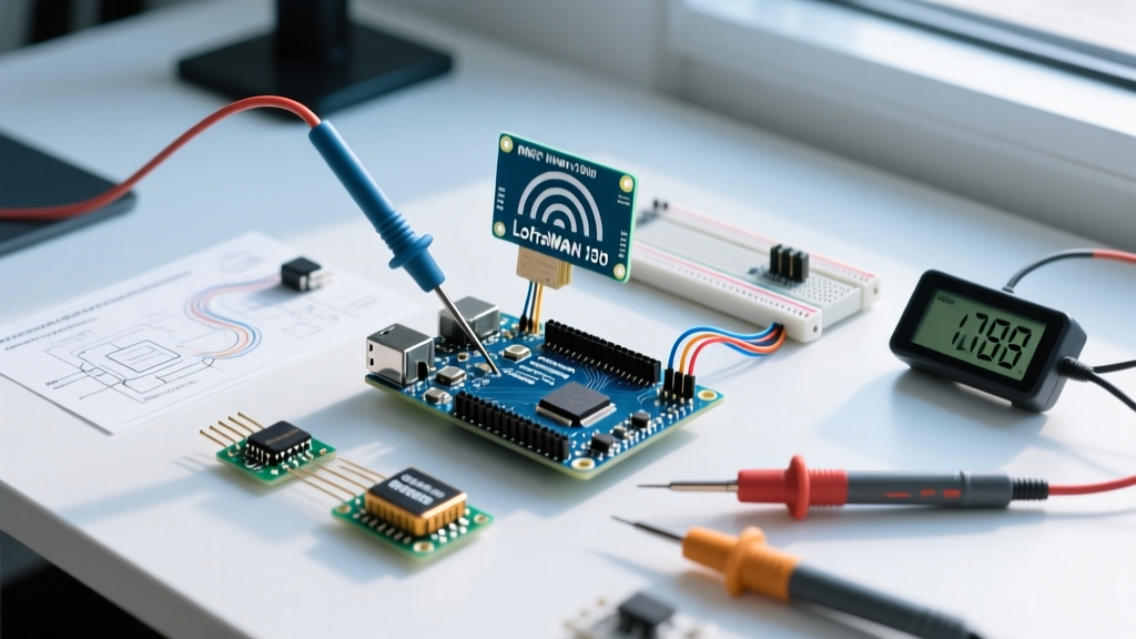
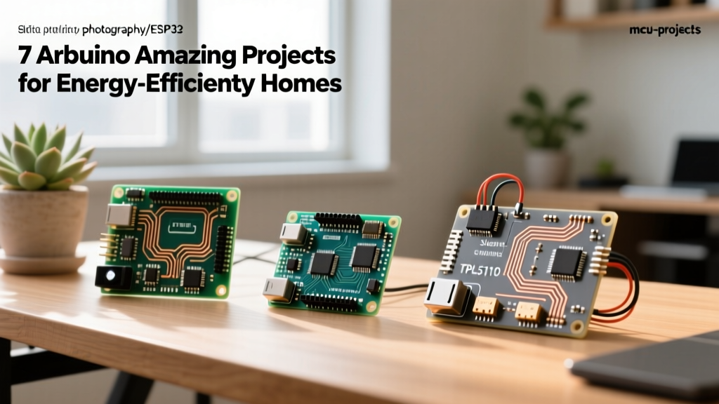
Software sleep modes are great, but hardware power-gating is bulletproof. The TPL5110 is a nano-power timer (Iq = 35nA) that acts as a physical switch, cutting power to your Arduino entirely between readings.
Hardware BOM & Cost (2026 Estimates)
- Arduino Pro Mini (ATmega328P, 3.3V/8MHz) - $2.50 (Regulator removed)
- Adafruit TPL5110 Breakout - $3.50 (See the Adafruit TPL5110 Power Timer Guide)
- BME280 I2C Sensor (Temp/Hum/Press) - $4.50
- 18650 LiPo Cell + Holder - $7.00
Wiring & Logic Flow
- Power Routing: Connect the 18650 positive terminal to the TPL5110 VIN. Connect TPL5110 VOUT to the raw VCC pin of the Pro Mini (bypassing the onboard regulator).
- The 'Done' Pin: Connect Arduino Digital Pin 4 to the TPL5110 'DONE' pin. When the Arduino finishes reading the BME280 and transmitting via LoRa, it drives Pin 4 HIGH. This tells the TPL5110 to physically sever the power circuit.
- Timing Resistor: Place a 250kΩ resistor between the TPL5110 DELAY pin and GND to set a wake-up interval of exactly 2 hours.
Power Math: The node wakes up, draws 15mA for 1.5 seconds to read the sensor and transmit a LoRa packet, then shuts off completely. Average current draw is roughly 12µA. A 2500mAh battery will theoretically power this node for 23 years (limited in reality by the 18650's self-discharge rate of ~2% per month, yielding a realistic lifespan of 4-5 years).
Project 2: ESP32 Solar Capacitive Soil Moisture Monitor
While the ATmega328P is king of low power, modern smart homes require Wi-Fi. The ESP32 is notoriously power-hungry, but its Deep Sleep mode makes solar-powered arduino amazing projects entirely feasible.
The DevKitC Trap
Never use a standard ESP32 DevKitC for battery projects. The onboard CP2102 USB-to-UART bridge and the AMS1117 regulator draw a combined ~15mA even when the ESP32 SoC is in deep sleep. Instead, use a bare ESP32-WROOM-32 module or a specialized low-power board like the FireBeetle ESP32-E, which uses a quiescent-efficient LDO and lacks the USB bridge.
Solar Harvesting Sizing
To run an ESP32 Wi-Fi transmission (which spikes to 350mA for 2 seconds) once every 4 hours via deep sleep, the average current is ~60µA.
- Daily Consumption: 60µA × 24h = 1.44mAh per day.
- Solar Panel Requirement: Assuming 2 hours of equivalent peak sunlight and a 70% charging efficiency via a TP4056 module, you need a panel capable of delivering at least 1.5mA at 5V. A standard 5V 200mA (1 Watt) micro-solar panel ($4.00) provides massive overhead, ensuring the node survives multi-week winter storms.
Project 3: Interrupt-Driven PIR Security Node
PIR (Passive Infrared) sensors like the AM312 are inherently low-power (drawing ~70µA). By pairing an AM312 with an ATtiny85 and utilizing hardware interrupts, you can build a security node that only wakes the MCU when human motion is detected.
Disabling the BOD (Brown-Out Detection)
The BOD circuit monitors voltage to prevent erratic behavior during brownouts, but it continuously draws ~15µA. For battery-powered security nodes, you must disable it via AVR fuse bits or in software right before entering sleep.
#include <avr/sleep.h>
#include <avr/power.h>

void enterSleep(void) {
  ADCSRA &= ~(1 << ADEN); // Disable ADC
  set_sleep_mode(SLEEP_MODE_PWR_DOWN);
  sleep_enable();
  // Disable BOD via software (ATmega328P specific)
  MCUCR |= (1 << BODS) | (1 << BODSE);
  MCUCR |= (1 << BODS);
  MCUCR &= ~(1 << BODSE);
  sleep_cpu(); // Execution halts here until INT0 triggers
}
Edge Cases: Hunting Parasitic Drain
Even with perfect code and hardware power-gating, makers often find their batteries dying prematurely. Here are the hidden culprits in IoT designs:
- I2C Pull-Up Resistors: Standard I2C buses use 4.7kΩ pull-up resistors to 3.3V. If your MCU sleeps but the sensor (like a BME280) remains powered, current will leak through the MCU's internal protection diodes via the I2C lines. Fix: Use a MOSFET (like the BSS138) to physically cut power to the I2C pull-ups and sensors during sleep.
- Floating GPIO Pins: Unconnected pins act as tiny antennas, picking up EMI and causing the internal CMOS logic gates to oscillate, drawing microamps of phantom current. Fix: Set all unused pins to
INPUT_PULLUPor configure them asOUTPUTdriven LOW before sleeping. - LED Indicators: A standard 3mm power LED with a 1kΩ resistor draws ~1.5mA. Over a month, this wastes over 1000mAh. Fix: Desolder power LEDs from all off-grid breakout boards.
Conclusion: The Future is Microamps
Building arduino amazing projects in 2026 is less about chaining together as many sensors as possible, and more about mastering the physics of power consumption. By selecting the right nano-power voltage regulators, utilizing hardware timers like the TPL5110, and ruthlessly eliminating parasitic drain, you can deploy autonomous, fire-and-forget IoT nodes that outlast the devices they are monitoring. True automation isn't just smart; it's sustainable.