
The Anatomy of Display Failures: Multiplexed vs. Serial Modules
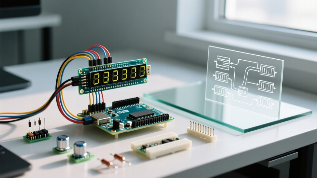
Integrating a four digit seven segment display Arduino setup is a rite of passage for embedded systems hobbyists and engineers. Whether you are building a precision PID temperature controller, a DIY frequency counter, or a retro-styled digital clock, these displays offer excellent visibility at a low cost. As of 2026, bare direct-multiplexed modules like the 3461BS (Common Cathode) or 5643AH (Common Anode) remain incredibly cheap at roughly $1.50 per 10-pack, while serial-driven TM1637 breakout boards average $1.80 to $2.50 each on major distributor sites.
However, driving these displays is notorious for introducing frustrating visual artifacts. Faint 'ghost' segments, seizure-inducing flicker, and uneven brightness are rarely hardware defects; they are almost always the result of timing violations, current starvation, or bus capacitance issues. This guide provides deep, actionable troubleshooting steps to resolve the most common failure modes in both direct-multiplexed and TM1637-based architectures.
Symptom 1: 'Ghosting' or Faint Segments on Unlit Digits
Ghosting occurs when segments that should be completely dark emit a faint glow. This is the most common issue when driving a bare four digit seven segment display with an Arduino using direct multiplexing.
Root Cause: Parasitic Capacitance and Pin State Overlap
LEDs possess minor parasitic capacitance, and the Arduino's GPIO pins do not switch states instantaneously. If your code updates the segment data pins before disabling the common pin of the previous digit, the new segment data briefly leaks into the old digit. Even a delay of 15 microseconds during the digitalWrite() execution is enough to cause visible ghosting at high multiplexing frequencies.
The 'Blanking' Sequence Fix
To eliminate ghosting, you must enforce a strict 'blanking' period. Never update segment pins while a common pin is active. Implement this exact 5-step sequence in your multiplexing loop:
- Turn off all segment pins: Set all 8 segment GPIOs to LOW (or HIGH, depending on Common Anode/Cathode).
- Disable the current common pin: Turn off the digit select line.
- Increment to the next digit index.
- Update the segment pins: Write the new byte/data for the next digit.
- Enable the new common pin: Turn on the digit select line.
Pro-Tip: StandarddigitalWrite()functions carry significant overhead (approx. 3-4 µs per call). For a 4-digit display, updating 12 pins sequentially can take over 40 µs. Replace standard writes with direct Port Manipulation (e.g.,PORTD = segmentData;) to execute the blanking sequence in a single clock cycle, completely eradicating ghosting.
Symptom 2: Severe Flickering and Visual Tearing
If your display looks like it is strobing or rolling, your refresh rate has dropped below the human eye's persistence of vision threshold, or your timing is being interrupted by blocking code.
Timer Interrupts vs. Blocking Delays
A common beginner mistake is using delay() or blocking sensor reads (like the DHT22 or ultrasonic HC-SR04) inside the main loop. Because multiplexing requires continuous, rapid updating, any blocking code halts the display refresh. According to the official Arduino millis() documentation, non-blocking timing is mandatory for concurrent peripheral management.
| Refresh Rate (Per Digit) | Overall Display Frequency | Visual Perception |
|---|---|---|
| < 30 Hz | < 120 Hz | Severe, distracting flicker |
| 60 Hz | 240 Hz | Slight flicker on peripheral vision |
| 120 Hz | 480 Hz | Solid, stable illumination (Ideal) |
| > 250 Hz | > 1000 Hz | Diminished brightness (Duty cycle loss) |
The Fix: Move the multiplexing logic to a Hardware Timer Interrupt (e.g., Timer1 on the ATmega328P). Set the timer to trigger every 2 milliseconds (yielding 125 Hz per digit). This ensures the display is refreshed in the background, entirely immune to blocking sensor reads in your void loop().
Symptom 3: Dim or Uneven Brightness Across Digits
If one digit appears noticeably dimmer than the others, or the entire display is too faint to read in ambient light, you are facing a current starvation or duty cycle problem.
The 25% Duty Cycle Reality
In a 4-digit multiplexed display, each digit is only powered 25% of the time. To achieve the perceived brightness of a continuous 20mA LED, the peak current during its active window must be much higher. However, the Microchip ATmega328P Datasheet strictly limits absolute maximum DC current per GPIO pin to 40mA, and the total VCC/GND package limit to 200mA. Pushing 80mA through a single Arduino pin to compensate for the duty cycle will permanently degrade the silicon.
Hardware Fix: Implement Transistor Drivers
Never drive the common (digit select) pins directly from the Arduino GPIO. Use bipolar junction transistors (BJTs) or MOSFETs to handle the heavy current sinking/sourcing.
- For Common Cathode (e.g., 3461BS): Use NPN transistors like the 2N2222 or BC547 on the 4 common pins. Connect the emitter to GND, the collector to the display common pin, and the base to the Arduino via a 1kΩ resistor.
- For Common Anode (e.g., 5643AH): Use PNP transistors like the 2N3906 or BC557. Connect the emitter to 5V, the collector to the common pin, and the base to the Arduino via a 1kΩ resistor (remember to pull the base HIGH to turn it OFF).
Resistor Sizing for Segments: Place current-limiting resistors on the 8 segment pins, not the common pins (to prevent brightness shifting when displaying '8' vs '1'). For a standard Red display (Vf = 1.8V) running at 5V logic with a target peak current of 20mA: R = (5V - 1.8V) / 0.020A = 160Ω. Use standard 150Ω or 180Ω resistors. For Blue/Green displays (Vf = 3.2V), use 82Ω or 100Ω resistors.
Symptom 4: TM1637 Serial Display Lockups and Bus Failures
The TM1637 module simplifies wiring to just four pins (VCC, GND, CLK, DIO), but it introduces I2C-like bus vulnerabilities. If your TM1637 display randomly freezes, drops digits, or fails to initialize, the issue is almost always signal integrity.
Parasitic Capacitance and Edge Rounding
The TM1637 protocol is not true I2C; it uses a custom 2-wire synchronous serial interface. The start condition requires the DIO line to transition LOW while the CLK line is HIGH. If your jumper wires exceed 15-20 cm, the parasitic capacitance of the wire rounds the sharp digital edges into slow analog curves. The TM1637 chip misinterprets this rounded edge as an invalid start condition and locks up.
Actionable Fixes:
- Shorten Wires: Keep CLK and DIO traces under 10 cm whenever possible.
- Add Pull-Up Resistors: While the TM1637 has internal pull-ups, they are notoriously weak (often >50kΩ) on clone chips. Solder external 4.7kΩ pull-up resistors from both the CLK and DIO lines to the 5V rail.
- Isolate Power Noise: Place a 100nF ceramic decoupling capacitor directly across the VCC and GND pins on the back of the TM1637 PCB. Motors and relays sharing the same 5V rail will inject back-EMF noise that crashes the TM1637's internal state machine.
Master Diagnostic Matrix
Use this quick-reference matrix to isolate your specific failure mode when troubleshooting your four digit seven segment display Arduino project.
| Visual Symptom | Primary Root Cause | Hardware / Software Fix |
|---|---|---|
| Faint 'Ghost' Segments | Pin state overlap during switching | Implement 5-step blanking sequence; use Port Manipulation |
| Strobing / Flickering | Blocking code in main loop | Move multiplexing to Hardware Timer Interrupt (Timer1) |
| Digit '8' is dimmer than '1' | Current bottleneck on common pin | Move resistors to segment lines; add BJT transistors to common pins |
| TM1637 Random Freezes | Capacitance rounding CLK/DIO edges | Add 4.7kΩ pull-ups; shorten wires; add 100nF decoupling cap |
| Single Dead Segment | Cold solder joint or blown GPIO | Test continuity with DMM; verify segment resistor value |
Advanced Verification: Using a Logic Analyzer
When visual troubleshooting fails, connect a cheap 8-channel USB logic analyzer (like the Saleae Logic clone, widely available for under $12) to your segment and common pins. Set the capture rate to 24 MHz. You will clearly see the 'dead time' between digit switches. If the common pin goes HIGH before the segment pins settle to their final LOW states, you have found your ghosting culprit. For TM1637 setups, the logic analyzer will reveal if the DIO start-condition is being corrupted by voltage sag or high-frequency noise from nearby switching regulators.
By respecting the electrical limits of the ATmega328P and adhering to strict timing protocols, you can transform a glitchy, flickering prototype into a robust, commercial-grade display interface. For further reading on managing concurrent tasks without blocking, the Adafruit Multiplexing Guide provides excellent foundational concepts on cooperative multitasking in embedded C++.