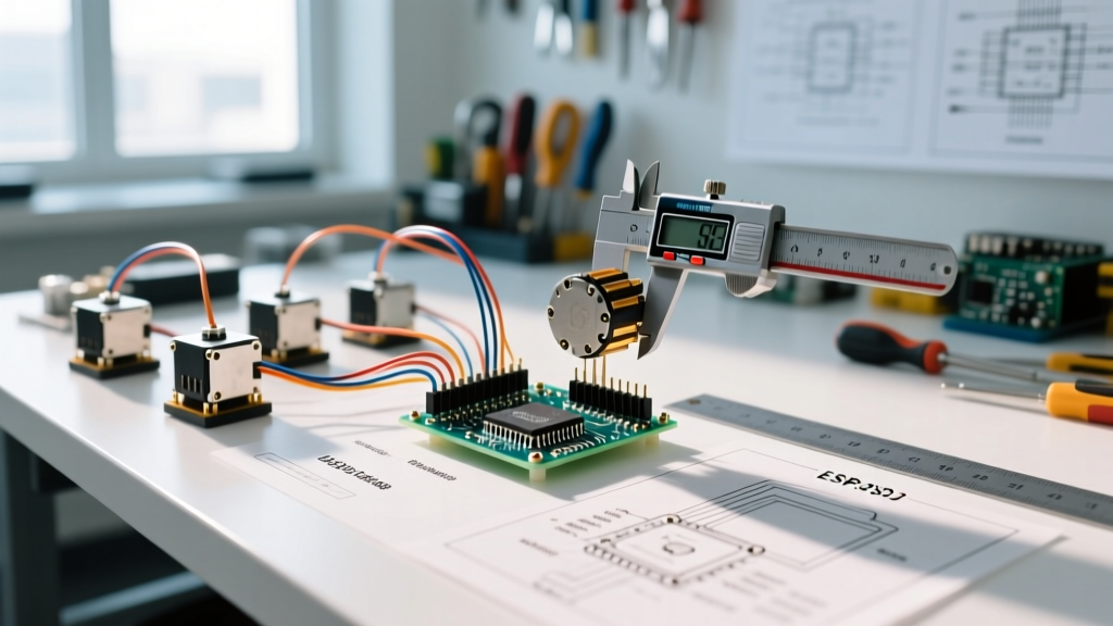

The Illusion of the 90-Degree Command
When you upload a basic sketch and command an Arduino servo motor to move to 90 degrees using myservo.write(90), you are operating on a foundational assumption: that the software's mathematical mapping perfectly aligns with the physical reality of the motor's internal potentiometer and gear train. In reality, this is rarely the case. For hobbyist applications like waving a robotic hand, a two-degree offset is negligible. But for CNC camera sliders, robotic arms, and automated throttles, this discrepancy leads to cumulative errors, mechanical binding, and failed projects.
The default Arduino Servo Library maps the 0-180 degree range to pulse widths between 544 and 2400 microseconds (µs). However, the physical hard stops of many standard servos actually occur at 500µs and 2500µs. By relying on the defaults, you are artificially restricting the servo's range and miscalibrating its midpoint. True precision requires a deliberate calibration protocol that accounts for PWM signal mapping, electrical noise, and mechanical backlash.
Hardware Selection: Matching Servo Physics to Project Needs
Calibration can only correct software mapping; it cannot fix poor hardware physics. Before writing a single line of calibration code, you must select a servo whose internal architecture supports your accuracy requirements. As of 2026, the market has shifted heavily toward digital and coreless motors for precision tasks, moving away from the analog hobby servos of the past decade.
| Model | Type | Deadband | Stall Torque (6V) | Avg. Price (2026) | Best Application |
|---|---|---|---|---|---|
| TowerPro SG90 | Analog / Plastic | ~5µs | 1.8 kg-cm | $2.50 - $4.00 | Basic prototyping, low-load indicators |
| Hi-Tec HS-645MG | Analog / Metal | ~4µs | 10.6 kg-cm | $35.00 - $42.00 | Heavy-duty RC, basic robotic joints |
| Savox SC1258MG | Digital / Coreless | ~1µs | 12.0 kg-cm | $45.00 - $55.00 | Precision gimbals, CNC end-effectors |
| Robotis Dynamixel XL330 | Smart / Digital | N/A (Serial) | 0.6 Nm | $25.00 - $30.00 | Multi-axis robotics, PID-controlled arms |
Notice the deadband specification. Analog servos like the SG90 have a wide deadband—the PWM pulse width must change by several microseconds before the motor's internal control board registers an error and applies power to the motor. Digital servos like the Savox SC1258MG sample the PWM signal at much higher frequencies, resulting in a tighter deadband and vastly superior holding accuracy. For projects demanding sub-degree accuracy, digital servos are mandatory.
Step-by-Step PWM Calibration Protocol
To achieve exact positioning, we must override the Arduino defaults and map the software to the physical limits of your specific servo unit. According to comprehensive RC servo guides from Pololu Robotics, the standard PWM frequency is 50Hz (a 20ms period), with the active pulse width dictating the position.
Phase 1: Discovering True Mechanical Limits
Do not guess your servo's limits. Forcing a servo past its internal mechanical stop will strip the plastic or brass gears and burn out the DC motor.
- Upload a Sweep Sketch: Modify the standard sweep code to output raw microsecond values using
writeMicroseconds()instead of degrees. - Find the Lower Bound: Start at 1500µs (center). Decrease the value by 10µs increments. Listen carefully. The moment you hear the motor humming against a physical hard stop without the horn moving, add 15µs. This is your true
MIN_PULSE(often around 500µs to 520µs). - Find the Upper Bound: Return to 1500µs. Increase by 10µs increments until you hear the hard stop hum. Subtract 15µs. This is your
MAX_PULSE(often 2450µs to 2500µs).
Phase 2: Software Remapping
Once you have your physical limits, you must pass them into the Arduino attach() function. This overrides the 544-2400µs default.
myservo.attach(SERVO_PIN, MIN_PULSE, MAX_PULSE);
By doing this, a command of myservo.write(0) will now send the exact MIN_PULSE you discovered, and myservo.write(180) will send the MAX_PULSE. The internal Arduino mapping will now linearly interpolate the degrees across your servo's actual physical travel.
Phase 3: Midpoint Verification
Command the servo to 90 degrees. Use a digital protractor or a precision machined square to verify the output shaft is exactly perpendicular to the mounting surface. If it is off by a degree or two, your servo's internal potentiometer is slightly misaligned from the factory. You can compensate for this in software by applying a global offset variable to your degree commands, or by physically removing the servo horn and re-seating it.
Eliminating Electrical Jitter and Ground Loops
You can have perfect software mapping, but if your power delivery is flawed, your Arduino servo motors will jitter, destroying your accuracy. A standard micro servo can draw 700mA to 1A during a stall condition. If you are powering the servo directly from the Arduino's 5V pin, the voltage will sag, causing the microcontroller to brownout and the PWM signal to degrade.
Expert Rule of Thumb: Never share a power rail between high-torque servos and sensitive logic circuits without proper decoupling. The inductive kickback from the servo's DC motor will inject high-frequency noise directly into your microcontroller's ground plane.
To stabilize the PWM signal and ensure positional accuracy, implement the following power architecture:
- Dedicated BEC (Battery Eliminator Circuit): Use a high-quality switching UBEC rated for at least 3A to step down your main battery voltage to 5V or 6V specifically for the servo power rail.
- Bulk Decoupling: Solder a 470µF electrolytic capacitor across the VCC and GND wires as close to the servo connector as possible. This acts as a local energy reservoir to handle transient current spikes during sudden directional changes.
- High-Frequency Filtering: Place a 0.1µF ceramic capacitor in parallel with the electrolytic capacitor to filter out high-frequency EMI generated by the servo's internal motor brushes.
- Common Ground: The ground wire from the BEC, the servo, and the Arduino MUST all be tied together. A missing common ground is the number one cause of erratic, full-speed servo spinning upon startup.
Compensating for Mechanical Backlash
Even high-end digital servos suffer from gear train backlash—the slight physical play between the teeth of the internal spur gears. If you command a servo to move to 45 degrees from 0 degrees, it might settle at 44.8 degrees. If you command it to 45 degrees from 90 degrees, it might settle at 45.2 degrees. This hysteresis is a mechanical reality detailed in advanced actuator guides by the Society of Robots.
Directional Approach Mapping
To achieve repeatable accuracy in CNC or plotting applications, you must eliminate backlash variables by always approaching your target position from the same direction. If your application requires the servo to push a tool against a surface, write a software routine that always approaches the target angle from the counter-clockwise direction. If the servo is currently past the target, command it to move 5 degrees past the target, pause for 100 milliseconds, and then move to the exact target. This forces the gear teeth to load against the same flank every single time, nullifying the dead space.
Troubleshooting Calibration Failures
When your calibrated setup still fails to hold position, use this diagnostic matrix to isolate the fault:
- Low-Frequency Oscillation (Hunting): The servo sweeps back and forth slowly around the target. Cause: The mechanical load is too close to the servo's stall torque, or the internal potentiometer is dirty/worn. Fix: Upgrade to a higher torque servo or reduce the mechanical leverage of your load.
- High-Frequency Jitter (Buzzing): The servo vibrates rapidly in place. Cause: PWM signal noise or inadequate power decoupling. Fix: Check your logic analyzer readings for PWM pulse width variance. If the Arduino's pulse width varies by more than 2µs, add a physical pull-up resistor on the PWM line or isolate the servo power supply.
- Thermal Drift: The servo is accurate when cold, but drifts by 2-3 degrees after 10 minutes of use. Cause: The internal potentiometer's resistance changes with heat. Fix: Switch to a servo with a magnetic encoder or a coreless motor that runs cooler.
Calibrating Arduino servo motors is not a one-time software trick; it is a holistic process of aligning code, electrical engineering, and mechanical physics. By abandoning default library assumptions, properly decoupling your power rails, and accounting for gear backlash, you can extract industrial-level precision from accessible hobbyist components.