
Understanding Pressure Sensors in Microcontroller Projects
When makers and engineers search for an Arduino pressure sensor, they are usually looking to solve one of two distinct physical problems: measuring atmospheric/barometric pressure for weather and altitude tracking, or measuring differential/gauge pressure for fluid dynamics, HVAC systems, and pneumatic actuators. Treating these two categories as interchangeable is the most common beginner mistake, leading to destroyed components and inaccurate data.
In this comprehensive interfacing tutorial, we will bypass generic overviews and dive directly into the hardware realities of integrating the two most ubiquitous pressure sensors in the DIY electronics ecosystem: the Bosch BMP280 (I2C barometric) and the NXP MPX5010DP (analog differential). By the end of this guide, you will understand exact wiring topologies, logic-level translation requirements, and the mathematical transfer functions required to extract reliable data.
Component Selection: Barometric vs. Differential Pressure
Before soldering a single header pin, you must match the sensor architecture to your physical environment. Barometric sensors measure absolute pressure relative to a vacuum, while differential sensors measure the pressure difference between two distinct ports.
| Feature | Bosch BMP280 (Barometric) | NXP MPX5010DP (Differential) | FlexiForce FSR402 (Mechanical) |
|---|---|---|---|
| Primary Use Case | Altitude, weather stations, drone telemetry | Airflow, CPAP machines, water level, pneumatics | Touch interfaces, weight scales, impact detection |
| Communication | I2C / SPI (Digital) | Analog Voltage (Ratiometric) | Analog Resistance (Voltage Divider) |
| Operating Voltage | 1.71V to 3.6V | 4.75V to 5.25V | 3.3V to 5V |
| Typical 2026 Cost | $3.50 - $5.00 (Breakout) | $8.00 - $12.00 (Raw IC) | $6.00 - $8.00 |
| Precision | ±1 hPa (Absolute) | ±2.5% Full Scale | Highly Non-Linear |
Project 1: Interfacing the BMP280 via I2C
The BMP280 is the industry standard for entry-level environmental sensing. However, its low operating voltage makes it a frequent victim of beginner wiring errors when paired with 5V microcontrollers like the Arduino Uno R3 or Mega 2560.
The 3.3V Logic Level Trap
Critical Hardware Warning: The BMP280 operates strictly at 3.3V. Connecting its I2C data lines (SDA/SCL) directly to the 5V digital pins of an ATmega328P-based Arduino will degrade the sensor's internal silicon over time, eventually causing permanent I2C bus lockups. Always use a bidirectional logic level shifter (like the BSS138 MOSFET-based modules) or a dedicated 3.3V Arduino board (like the Nano 33 IoT or MKR series).
I2C Wiring and Address Configuration
According to the Bosch Sensortec BMP280 Documentation, the sensor supports two distinct I2C addresses based on the state of the SDO (Serial Data Out) pin:
- 0x76: SDO tied to GND (Default on most Adafruit and generic breakout boards).
- 0x77: SDO tied to VCC (Used when multiplexing multiple sensors on the same bus).
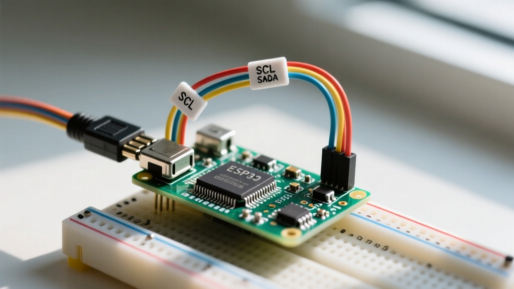
Wiring Topology (Using a 3.3V Arduino Nano 33 IoT):
- VIN: Connect to 3.3V output.
- GND: Connect to common ground.
- SCL: Connect to dedicated SCL pin (A5 on older boards, dedicated SCL header on newer layouts).
- SDA: Connect to dedicated SDA pin (A4 on older boards, dedicated SDA header).
When utilizing the Adafruit BMP280 Breakout Guide library, initialization requires specifying the exact I2C address. If your serial monitor outputs 'Could not find a valid BMP280 sensor', run an I2C scanner sketch to verify if your specific breakout board defaults to 0x77 instead of 0x76.
Project 2: Analog Differential Pressure with MPX5010DP
While barometric sensors dominate weather projects, the NXP MPX5010DP is the workhorse for measuring physical pressure differentials up to 10 kPa (roughly 1.45 PSI). This 6-pin DIP package outputs an analog voltage proportional to the pressure applied between its P1 (high) and P2 (low) ports.
Hardware Signal Conditioning (RC Filtering)
The raw output of the MPX5010DP is notoriously susceptible to high-frequency electromagnetic interference (EMI) and power supply ripple. Feeding this directly into the Arduino's 10-bit ADC will result in jittery, unusable data. You must implement a hardware low-pass RC filter before the signal reaches the microcontroller.
Recommended Filter Topology:
- Connect MPX5010DP Pin 1 (Vout) to a 10kΩ resistor.
- Connect the other end of the resistor to the Arduino Analog Pin (A0).
- Place a 100nF (0.1µF) ceramic capacitor between the Arduino Analog Pin (A0) and GND.
This creates a single-pole low-pass filter with a cutoff frequency of approximately 159 Hz, effectively eliminating switching noise from nearby DC-DC converters and servo motors while preserving the relatively slow-changing pressure data.
The MPX5010 Transfer Function and Code
Unlike digital sensors that handle math internally, analog sensors require you to implement the manufacturer's transfer function in your firmware. Based on the NXP MPX Series Datasheet, the ideal transfer equation is:
Vout = Vs * (0.09 * P + 0.095)
Where Vs is the supply voltage (5.0V) and P is the pressure in kPa. To find the pressure, we must invert this formula in our Arduino sketch:
P = ((Vout / 5.0) - 0.095) / 0.09
Implementation Snippet:
const int sensorPin = A0;
const float Vref = 5.0; // Use actual measured 5V rail for precision

void setup() {
  Serial.begin(115200);
  analogReadResolution(10); // Standard for Uno/Mega
}

void loop() {
  // Oversample to reduce ADC noise
  long sum = 0;
  for(int i = 0; i < 64; i++) {
    sum += analogRead(sensorPin);
    delayMicroseconds(200);
  }
  float avgADC = sum / 64.0;

  // Convert ADC value to Voltage
  float voltage = (avgADC / 1023.0) * Vref;

  // Apply inverted transfer function
  float pressure_kPa = ((voltage / Vref) - 0.095) / 0.09;

  // Clamp negative noise floor
  if(pressure_kPa < 0) pressure_kPa = 0;

  Serial.print("Pressure: ");
  Serial.print(pressure_kPa);
  Serial.println(" kPa");
  delay(100);
}
Advanced Troubleshooting and Edge Cases
Even with correct wiring, sensor integration often fails due to environmental and electrical edge cases. Here is how to diagnose the most common issues:
- I2C Bus Capacitance Limits: If you are running long wires (over 30cm) to a BMP280, the parasitic capacitance of the cable will degrade the I2C square waves, causing data corruption. Arduino Wire (I2C) Reference guidelines suggest lowering the I2C clock speed from 400kHz to 100kHz using
Wire.setClock(100000);in your setup loop. - MPX5010 Ratiometric Errors: The MPX5010 output is ratiometric to its supply voltage. If your Arduino's 5V rail is actually dropping to 4.7V under load (common when powering servos or LEDs), your pressure calculations will drift. Always measure the actual VCC rail with a multimeter and update the
Vrefconstant in your code accordingly. - Condensation in Pneumatic Lines: When using differential sensors to measure water tank levels via hydrostatic head pressure, moisture condensation inside the silicone tubing will block the sensor port. Always install a 0.2-micron PTFE hydrophobic membrane filter between the tubing and the sensor port to protect the internal silicon die.
Frequently Asked Questions
Can I use a BMP280 to measure water depth?
No. The BMP280 is designed for atmospheric gases. Submerging it or exposing its internal MEMS element to liquid water will cause immediate short-circuiting and corrosion. For hydrostatic liquid depth, use a sealed differential sensor like the MPX5010DP with an air-filled reference tube.
Why is my BMP280 altitude reading drifting by 10 meters a day?
Barometric altitude is calculated relative to a fixed sea-level pressure baseline (usually 1013.25 hPa). Because weather systems naturally cause sea-level pressure to fluctuate by up to 30 hPa over a few days, your calculated altitude will drift. For static installations, you must recalibrate the sea-level baseline daily or use a GPS module to lock the true altitude.