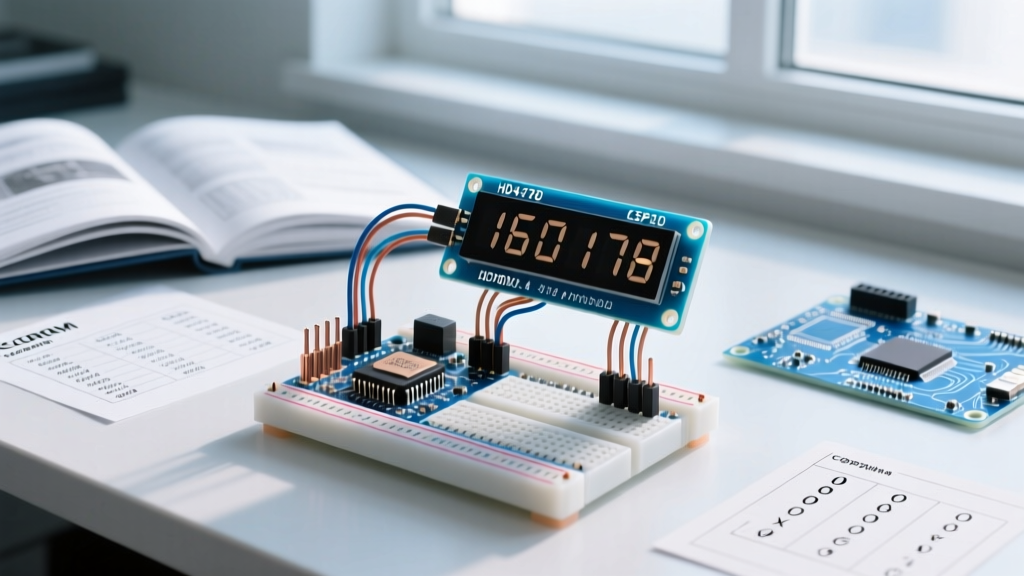

Why Upgrade to a Time of Flight Sensor Arduino Setup?
For years, the HC-SR04 ultrasonic module has been the default choice for hobbyist distance measurement. However, as robotics and automation projects demand higher precision, ultrasonic sensors reveal critical flaws: a wide 30-degree acoustic beam that causes false positives, susceptibility to temperature fluctuations, and an inability to detect sound-absorbing materials like foam or fabric. Enter the time of flight sensor Arduino integration, specifically utilizing STMicroelectronics' VCSEL (Vertical-Cavity Surface-Emitting Laser) technology.
Unlike acoustic echolocation, ToF sensors emit a concentrated 940nm infrared laser pulse and measure the exact time it takes for photons to bounce back to a SPAD (Single-Photon Avalanche Diode) array. This yields millimeter-level accuracy, a narrow field of view, and immunity to acoustic noise. In this comprehensive guide, we will focus on the VL53L1X, the industry-standard long-range ToF module, and walk through advanced wiring, timing budget configurations, and real-world optical edge cases.
Choosing the Right STMicroelectronics ToF Module
Before soldering headers, it is crucial to select the correct sensor generation for your specific application. As of 2026, bare VL53L1X chips hover around $4.50, while fully regulated breakout boards from manufacturers like Pololu or Adafruit retail between $9.00 and $12.50. Below is a technical comparison of the three most common ST ToF sensors available on the market.
| Model | Max Range | Accuracy | Best Use Case | Avg Breakout Price |
|---|---|---|---|---|
| VL53L0X (Gen 1) | 2.0 meters | ±3% to ±5% | Basic obstacle avoidance, indoor robotics | $5.00 - $7.00 |
| VL53L1X (Gen 2) | 4.0 meters | ±1% to ±3% | Drones, long-range proximity, liquid level sensing | $9.00 - $12.50 |
| VL53L4CD (Gen 3) | 1.3 meters | ±1mm absolute | Precision manufacturing, short-range autofocus | $6.50 - $9.50 |
Source: Pricing and specifications aggregated from the STMicroelectronics VL53L1X product page and major electronics distributors.
Hardware Wiring: I2C and the Critical XSHUT Pin
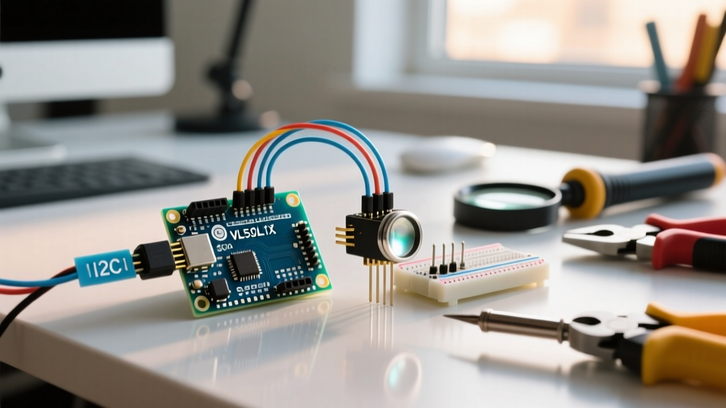
The VL53L1X communicates via I2C and ships with a default 7-bit address of 0x29. While wiring VCC, GND, SDA, and SCL is straightforward, ignoring the XSHUT (Shutdown) pin is the number one cause of failure in multi-sensor arrays.
Standard Single-Sensor Pinout
- VIN / VCC: Connect to 5V if using a breakout board with an onboard LDO regulator (like the Pololu VL53L1X carrier). Connect directly to 3.3V if using a raw module.
- GND: Common ground with your Arduino.
- SDA / SCL: Connect to Arduino I2C pins (A4/A5 on Uno, D20/D21 on Mega). Note: The VL53L1X requires 2.8V logic. Ensure your breakout has logic level shifters if using a 5V Arduino.
- GPIO1: Interrupt output (optional, used for data-ready signaling).
- XSHUT: Active HIGH. Must be pulled to VIN or 3.3V to operate. If left floating, the sensor may enter an erratic sleep state.
Multi-Sensor Multiplexing via XSHUT
Because ST hardcodes the default I2C address to 0x29, connecting two sensors to the same I2C bus will cause a collision. You must use the XSHUT pin to sequence their initialization:
- Connect the XSHUT pin of every sensor to a separate digital GPIO pin on the Arduino.
- Set all XSHUT pins to
LOWin yoursetup()function. This puts all sensors into hardware standby. - Pull Sensor 1's XSHUT
HIGH, initialize it via I2C, and use the library to change its I2C address to0x30. - Pull Sensor 2's XSHUT
HIGH, initialize it, and change its address to0x31. - Repeat for additional sensors. Warning: I2C addresses are volatile and reset to
0x29whenever the XSHUT pin drops low or power is cycled.
Arduino Code: Configuring Timing Budgets and ROI
When programming a time of flight sensor Arduino project, the Pololu VL53L1X library is highly recommended for its clean abstraction of ST's complex API. The two most critical parameters you must configure are the Distance Mode and the Timing Budget.
Expert Insight: The Timing Budget is the exact time allowance (in microseconds) the sensor dedicates to capturing photon returns. A longer budget increases maximum range and accuracy in low-reflectivity environments but decreases the maximum polling rate.
#include <Wire.h>
#include <VL53L1X.h>

VL53L1X sensor;

void setup() {
  Wire.begin();
  Wire.setClock(400000); // 400kHz I2C Fast Mode
  Serial.begin(115200);

  // Initialize sensor and check for timeout
  sensor.setTimeout(500);
  if (!sensor.init()) {
    Serial.println("Failed to detect and initialize sensor!");
    while (1);
  }

  // Set Long Distance Mode (up to 4m)
  sensor.setDistanceMode(VL53L1X::Long);

  // Set Timing Budget to 50ms (50000 microseconds)
  sensor.setMeasurementTimingBudget(50000);

  // Start continuous readings with 100ms inter-measurement period
  sensor.startContinuous(100);
}

void loop() {
  Serial.print(sensor.read());
  Serial.print(" mm");
  if (sensor.timeoutOccurred()) { Serial.print(" TIMEOUT"); }
  Serial.println();
}
For high-speed robotics, drop the timing budget to 20000 (20ms) and switch to VL53L1X::Short mode. For static liquid-level monitoring, increase the budget to 100000 (100ms) to average out surface ripples. For deeper understanding of I2C bus speeds and clock stretching during these reads, consult the Arduino Wire library reference.
Edge Cases: Cover Glass Crosstalk and IR Interference
Deploying ToF sensors in commercial or outdoor enclosures introduces optical physics problems that standard tutorials ignore.
The Cover Glass Crosstalk Problem
If you place a transparent acrylic or glass window in front of the VL53L1X to protect it from dust, a portion of the 940nm laser will reflect off the inner surface of the glass directly back into the SPAD receiver. This is called internal crosstalk. The sensor will interpret this immediate reflection as an object sitting 5mm away, completely blinding it to actual targets.
The Fix: You must perform a crosstalk calibration. Using the ST API, trigger the VL53L1_SetXtalk() function while pointing the sensor at a target exactly 100mm away behind your chosen cover glass. The sensor will calculate the internal reflection offset and subtract it from all future readings. Additionally, use an opaque mechanical shroud between the TX and RX apertures on the sensor face.
Sunlight and 940nm Saturation
The sun emits massive amounts of broadband infrared light, including the 940nm wavelength used by the VL53L1X. In direct outdoor sunlight, the ambient IR noise floods the SPAD array, dropping the maximum reliable range from 4 meters down to roughly 0.8 meters.
The Fix: For outdoor time of flight sensor Arduino builds, you must either machine a deep physical hood (shroud) to block off-axis sunlight, or install a narrow-band 940nm optical bandpass filter over the receiver aperture. Note that adding a bandpass filter will reduce overall signal transmission by ~15%, requiring a slight increase in your timing budget.
Troubleshooting Matrix
Use this diagnostic table to resolve common integration anomalies:
| Symptom | Root Cause | Engineering Solution |
|---|---|---|
Sensor constantly reads 8190 or 8191 mm |
Target is out of range, or photon return rate is below the signal-to-noise threshold. | Increase Timing Budget to 100ms. Ensure target surface is not highly absorptive (e.g., black velvet). |
I2C Scanner finds no devices at 0x29 |
XSHUT pin is floating or pulled LOW; missing I2C pull-up resistors. | Verify XSHUT is tied to 3.3V. Add 4.7kΩ pull-up resistors to SDA and SCL lines if using raw chips. |
| Readings jump erratically indoors (±50mm variance) | Interference from 120Hz fluorescent lighting or high-frequency LED drivers. | Enable the ambient light flicker rejection algorithm in the ST API (SetVcselPulsePeriod adjustments). |
| Readings are stuck at ~4mm regardless of target | Severe cover glass crosstalk or smudged TX/RX apertures. | Clean the sensor face with isopropyl alcohol. Run ST crosstalk calibration routine with the enclosure installed. |
Final Integration Advice
Integrating a time of flight sensor Arduino setup elevates your project from hobbyist prototyping to industrial-grade spatial awareness. By respecting the optical physics of the VCSEL emitter, properly managing I2C addresses via the XSHUT pin, and tuning your timing budgets to match your mechanical environment, the VL53L1X will deliver flawless, sub-centimeter accuracy for years of continuous operation.