
Decoding the Silicon: Why the Datasheet Matters
When integrating an Arduino and LCD display, most makers rely entirely on the LiquidCrystal or LiquidCrystal_I2C libraries without ever questioning the underlying hardware protocols. While these libraries abstract away the complexity, they also hide the precise timing and memory management rules dictated by the display's silicon. In 2026, with supply chains flooded with clone controllers and varying I2C backpack implementations, blindly trusting library defaults often leads to dropped characters, initialization failures, and ghosting.
This guide bypasses the high-level abstractions and dives directly into the Hitachi HD44780 controller datasheet and the NXP PCF8574 I2C expander datasheet. By understanding the exact memory maps, execution timings, and electrical characteristics, you can troubleshoot edge cases and optimize your display code for mission-critical embedded applications.
Anatomy of the HD44780: DDRAM, CGROM, and CGRAM
The HD44780 controller does not render pixels directly; it manages memory arrays that map to the physical liquid crystal matrix. According to the official HD44780 datasheet, the chip utilizes three distinct memory types:
- DDRAM (Display Data RAM): Stores the character codes currently being displayed. It holds up to 80 characters, but only a subset is visible on the screen at any given time.
- CGROM (Character Generator ROM): Contains the hardwired 5x8 dot font patterns for 208 standard ASCII and Japanese Katakana characters.
- CGRAM (Character Generator RAM): A volatile 64-byte memory space allowing users to define up to eight custom 5x8 characters.
The DDRAM Addressing Trap
The most common point of failure when upgrading from a 16x2 display to a 20x4 display is the non-linear DDRAM addressing. The datasheet specifies that row addresses do not increment sequentially. If you attempt to write a continuous string of 80 characters, the text will wrap in an illogical order (Row 1 -> Row 3 -> Row 2 -> Row 4).
| Display Format | Row 1 Base | Row 2 Base | Row 3 Base | Row 4 Base |
|---|---|---|---|---|
| 16x2 | 0x00 | 0x40 | N/A | N/A |
| 20x2 | 0x00 | 0x40 | N/A | N/A |
| 16x4 | 0x00 | 0x40 | 0x10 | 0x50 |
| 20x4 | 0x00 | 0x40 | 0x14 | 0x54 |
Actionable Insight: When writing custom I2C drivers, you must manually send the 'Set DDRAM Address' command (0x80 + Base Address) before writing to a new row. Relying on auto-increment across rows will result in corrupted display output.
The 4-Bit Initialization Handshake
The datasheet outlines a strict initialization sequence to force the controller into 4-bit mode. Upon power-up, the HD44780 defaults to 8-bit mode. If your Arduino is only wired using 4 data pins (D4-D7), you must perform a specific hardware handshake to synchronize the bus.
The Magic Sequence (0x33, 0x32):
1. Send 0x03 (Wait >4.1ms)
2. Send 0x03 (Wait >100μs)
3. Send 0x03 (Wait >100μs)
4. Send 0x02 (Switches to 4-bit mode)
5. Send 0x28 (Function Set: 4-bit, 2 lines, 5x8 font)
Many lightweight, third-party Arduino libraries skip the initial 4.1ms delay to save boot time. In environments with slow-rising 5V rails or high capacitance on the breadboard, skipping this delay causes the LCD to latch into an undefined state, resulting in a permanently frozen top row of solid blocks.
Timing Parameters: Why Your LCD Drops Characters
Microcontrollers operating at 16MHz or higher can easily outpace the HD44780's internal oscillator (typically 272kHz). The datasheet defines critical timing parameters that dictate how fast you can push data:
Enable Pulse Width ($t_{pw}$)
The Enable (E) pin acts as the clock signal for parallel data transfer. The datasheet mandates a minimum Enable pulse width of 450 nanoseconds. While a 16MHz Arduino executes a digitalWrite() toggle in roughly 600ns, adding wire capacitance can degrade the signal edge. If you are bit-banging the LCD on an ESP32 or higher-speed MCU, you must insert a delayMicroseconds(1) between setting E HIGH and E LOW.
Execution Time ($t_{c}$)
Not all commands are created equal. While writing a character to DDRAM takes a mere 43μs, the 'Clear Display' and 'Return Home' commands require 1.52ms. If your code loops rapidly and issues a clear command without a blocking delay or a busy-flag check, subsequent characters will be dropped or written to incorrect memory addresses.
Pro-Tip: Polling the Busy Flag (BF)Instead of relying on hardcoded delay() functions, advanced firmware should read the Busy Flag. By setting the R/W pin HIGH and reading D7, the Arduino can determine exactly when the HD44780 has finished processing the last instruction. This optimizes loop execution time, though it requires sacrificing an extra GPIO pin, which is why I2C backpacks are preferred in modern designs.
The Modern Standard: PCF8574 I2C Backpacks
In 2026, direct parallel wiring is largely reserved for legacy maintenance or extreme high-speed refresh requirements. The standard for Arduino and LCD projects is the I2C backpack, typically built around the NXP PCF8574 or Texas Instruments equivalent. This 8-bit I/O expander translates I2C serial data into the parallel signals required by the HD44780.
The I2C Addressing Confusion
A frequent source of frustration is the I2C address mismatch. Makers often run an I2C scanner sketch, only to find their backpack responding at an unexpected address. This stems from the difference between the PCF8574 and the PCF8574A variant:
- PCF8574 (NXP): Base address is
0x20. With A0, A1, A2 jumpered, addresses range from 0x20 to 0x27. - PCF8574A (NXP/TI): Base address is
0x38. With A0, A1, A2 jumpered, addresses range from 0x38 to 0x3F.
If your library is hardcoded to 0x27 but your backpack uses the 'A' silicon variant, the display will remain blank. Always verify the exact chip silkscreen on the backpack PCB.
I2C Pull-Up Resistors and Bus Capacitance
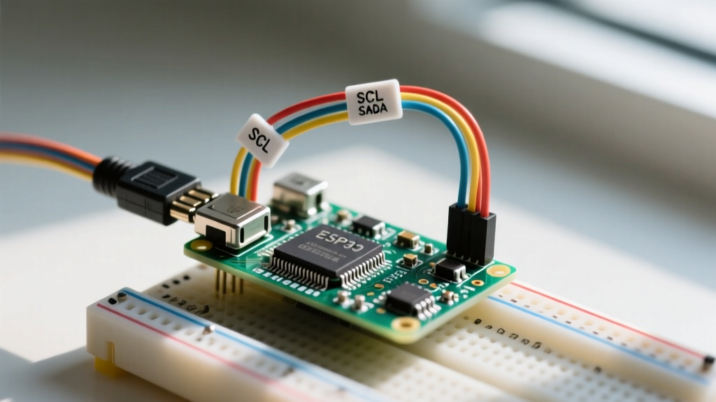
The PCF8574 utilizes open-drain outputs for the I2C SDA and SCL lines. According to the Arduino I2C communication guide, the internal pull-up resistors on the ATmega328P (typically 20kΩ to 50kΩ) are often too weak to pull the lines HIGH quickly enough when driving long wires or multiple devices. For reliable operation at 100kHz or 400kHz, install external 4.7kΩ pull-up resistors on both SDA and SCL lines tied to the 5V rail.
Hardware Pitfalls: V0, VDD, and Backlight Currents
Datasheets provide absolute maximum ratings and typical operating circuits that are frequently ignored in DIY tutorials, leading to hardware degradation.
The V0 Contrast Voltage
The V0 pin controls the liquid crystal bias voltage. It does not simply take a 0-5V analog signal. For a standard 5V STN negative-mode display, the optimal V0 voltage is typically between 0.5V and 1.0V relative to VSS (Ground). Using a standard 10kΩ potentiometer wired as a voltage divider between 5V and GND works, but it wastes current. A more precise, space-saving approach is to use a fixed resistor divider (e.g., 1kΩ to VSS and 220Ω to VDD) or connect V0 directly to GND if the module features an onboard contrast trimmer.
Backlight LED Forward Voltage
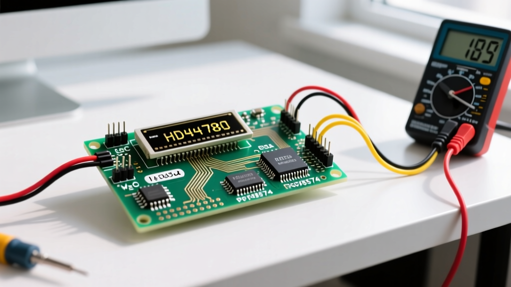
Pin 15 (LED+) and Pin 16 (LED-) drive the backlight. The datasheet specifies a typical forward voltage ($V_f$) of 4.1V and a maximum forward current ($I_f$) of 30mA (typical 20mA). Never connect 5V directly to Pin 15. Doing so will exceed the current rating, causing rapid thermal degradation of the LEDs. Calculation: $R = (V_{source} - V_f) / I_f = (5.0V - 4.1V) / 0.020A = 45Ω$. Always use a 47Ω or 56Ω current-limiting resistor in series with the anode. Many cheap I2C backpacks omit this resistor on the PCB; you must verify its presence with a multimeter before applying power.
Frequently Asked Questions
Can I power a 5V HD44780 LCD with a 3.3V Arduino?
Technically, the HD44780 requires a minimum VDD of 4.5V for guaranteed operation. While some clones will boot at 3.3V, the internal oscillator frequency drops, invalidating standard library timing delays. Furthermore, the 3.3V logic HIGH from the Arduino may fall below the HD44780's $V_{IH}$ (Input High Voltage) threshold of 2.2V when noise is present. Always use a bidirectional logic level shifter or a dedicated 5V I2C backpack powered from the Arduino's 5V pin.
Why does my custom CGRAM character print as a random symbol?
CGRAM addresses are limited to 0x00 through 0x07. If you attempt to map a custom character to index 8 or higher, the controller wraps the address or reads from unmapped memory. Additionally, you must switch the cursor back to DDRAM mode (using the 0x80 command) after defining your custom character, or subsequent text will overwrite your custom font data.
Is I2C too slow for real-time data logging displays?
At standard 100kHz I2C speeds, updating a full 16x2 screen (32 bytes) takes roughly 3.5 milliseconds, accounting for ACK bits and overhead. At 400kHz (Fast Mode), this drops to under 1 millisecond. For human-readable data logging, I2C bandwidth is more than sufficient. However, if you are rendering high-frequency waveforms or oscilloscope traces, you must abandon the HD44780 entirely in favor of SPI-driven graphic OLED or TFT displays.