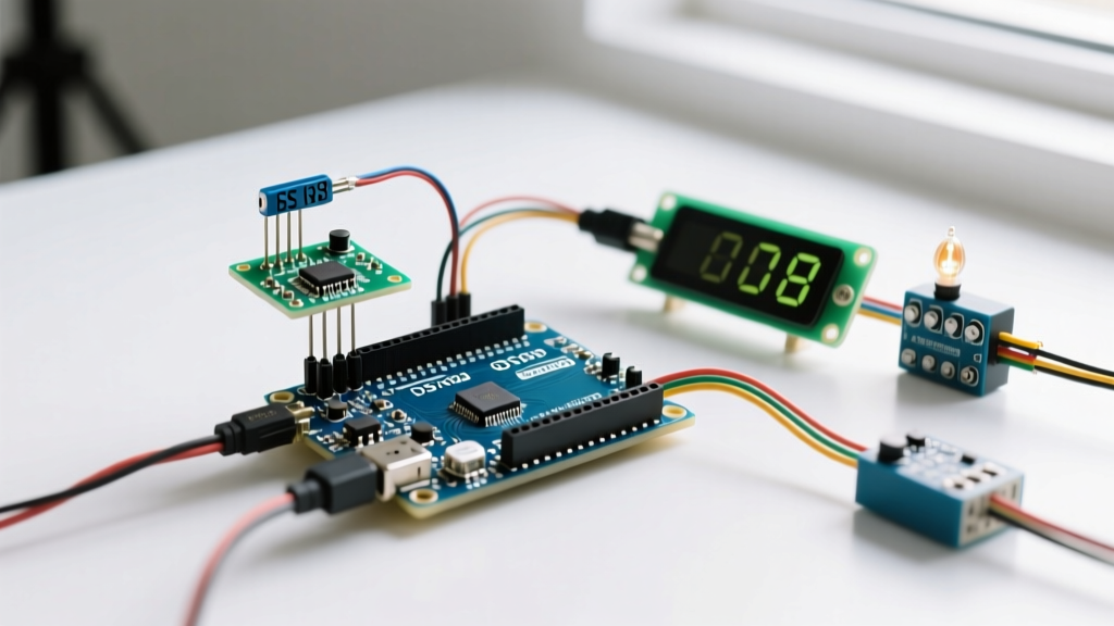

The I2C Bus Bottleneck in Complex Arduino Projects
Building a standalone temperature monitor is a beginner milestone, but integrating a high-precision thermometer sensor Arduino setup into a multi-peripheral environment requires a completely different engineering approach. In 2026, modern DIY robotics, environmental chambers, and automated brewing systems rarely rely on a single sensor. Your microcontroller is likely simultaneously driving an OLED telemetry display, triggering a PCA9685 servo driver, and polling a thermometer sensor.
When you daisy-chain multiple peripherals onto the same I2C or 1-Wire bus, you introduce three critical failure vectors: bus capacitance overload, address collisions, and power rail brownouts. This guide bypasses basic wiring tutorials and dives deep into the electrical engineering realities of multi-peripheral sensor integration, ensuring your thermometer data remains stable even when high-current relays switch on.
Choosing the Right Thermometer Sensor Module
Not all temperature sensors behave identically under multi-device bus loads. Selecting the correct module dictates your wiring topology and logic-level requirements.
| Sensor Model | Interface | Accuracy | Bus Load Impact | Typical 2026 Price |
|---|---|---|---|---|
| DS18B20 (Maxim) | 1-Wire | ±0.5°C | High (Requires strict timing & dedicated pull-up) | $3.50 - $5.00 |
| TMP117 (Texas Instruments) | I2C | ±0.1°C | Low (Standard I2C node, low capacitance) | $12.00 - $15.00 |
| BME280 (Bosch) | I2C / SPI | ±1.0°C | Medium (Supports SPI offloading) | $8.00 - $11.00 |
For high-stakes multi-peripheral setups where I2C bus space is at a premium, the TMP117 is the superior choice. Its medical-grade accuracy and standard I2C compliance make it highly predictable. If your I2C bus is already saturated, utilizing the BME280 via SPI moves the thermometer sensor Arduino traffic off the I2C bus entirely, freeing up bandwidth for your displays and motor controllers.
Resolving I2C Bus Capacitance and Signal Degradation
The most common reason a thermometer sensor Arduino setup fails in a multi-peripheral environment is I2C bus capacitance. According to the official NXP I2C-bus specification, the maximum allowable bus capacitance is 400 pF. Every wire, breadboard trace, and peripheral module adds parasitic capacitance. An OLED display might add 15 pF, while long unshielded jumper cables can add 2 pF per centimeter. When capacitance exceeds 400 pF, the rising edges of the SCL and SDA signals become sluggish, causing the microcontroller to misinterpret bits and drop the sensor connection entirely.
Calculating Pull-Up Resistor Values for Multi-Drop Buses
To combat high capacitance, you must lower the resistance of your I2C pull-up resistors to charge the bus faster. The standard 4.7kΩ resistors included on most Arduino sensor breakouts are insufficient for multi-device setups. Use the following formula to find your minimum pull-up resistance:
Rp(min) = (Vcc - Vol) / Iol
Where Vcc is 5V, Vol (max low-level output voltage) is 0.4V, and Iol (max sink current) is 3mA.
Rp(min) = (5 - 0.4) / 0.003 = 1,533Ω
In a complex setup with an OLED, a TMP117 thermometer, and an RTC module, replace the default 4.7kΩ pull-ups with 2.2kΩ or 1.5kΩ resistors. This ensures sharp signal edges even with 30cm+ wire runs.
Address Collisions and the TCA9548A Multiplexer
If your project requires multiple thermometer sensors (e.g., monitoring ambient, liquid, and exhaust temperatures), you will quickly hit I2C address limitations. Many popular sensors have hardcoded addresses or only offer a single alternate address via a jumper pad.
Instead of hacking traces on the PCB, integrate a TCA9548A I2C Multiplexer (typically $4.50). This chip sits on the main I2C bus and creates eight isolated sub-buses. Crucially, the TCA9548A also isolates bus capacitance. The 400 pF limit applies only to the main bus and the currently selected sub-bus, allowing you to wire significantly more peripherals without degrading signal integrity. Referencing the Arduino Wire library documentation, you can switch multiplexer channels in software before polling each specific thermometer sensor.
Power Budgeting: Avoiding Brownouts and Logic Mismatches
Multi-peripheral setups draw significant current. A standard 5V relay module can pull 70mA to 150mA when the coil energizes. If your thermometer sensor shares the same 5V rail without proper decoupling, the voltage dip during relay switching can cause the sensor to reset or output corrupted hexadecimal data.
Logic Level Shifting for 3.3V Sensors
Modern high-precision sensors like the TMP117 operate strictly at 3.3V logic. If you are using a 5V Arduino Uno R4 Minima or Mega2560, sending 5V SDA/SCL signals directly into a 3.3V sensor will degrade the silicon over time and cause I2C ACK failures. You must use a BSS138-based bidirectional logic level shifter between the 5V microcontroller and the 3.3V thermometer sensor.
- Decoupling: Place a 100nF ceramic capacitor and a 10μF tantalum capacitor directly across the VCC and GND pins of the thermometer sensor breakout board.
- Parasitic Power Warning: Never use the 'parasitic power' mode of a DS18B20 in a multi-peripheral setup. The 4.7kΩ pull-up resistor cannot source the 1.5mA required during the active temperature conversion phase if other devices are simultaneously pulling on the bus. Always wire a dedicated VDD line.
Step-by-Step Wiring: TMP117, OLED, and Relay Module
Here is a robust wiring topology for a 5V Arduino Uno R4 Minima managing a 3.3V TMP117 thermometer sensor, a 1.3-inch SH1106 I2C OLED, and a 5V opto-isolated relay.
- Power Rails: Connect the Arduino 5V and GND to the main breadboard power rails. Use a dedicated buck converter (like an LM2596 module set to 3.3V) to create a secondary 3.3V rail for the logic side.
- Level Shifter: Wire the BSS138 level shifter. Connect LV to the 3.3V rail, HV to the 5V rail. Connect Arduino SDA/SCL to HV1/HV2.
- Thermometer Sensor: Connect the TMP117 SDA/SCL to LV1/LV2 on the shifter. Wire TMP117 VCC to the 3.3V rail and GND to ground. Add the 100nF decoupling capacitor.
- OLED Display: Since most SH1106 OLEDs are 5V tolerant, wire their SDA/SCL directly to the Arduino 5V I2C bus (HV side). Install a 2.2kΩ pull-up resistor between the 5V rail and the SDA/SCL lines.
- Relay Module: Power the relay VCC directly from the Arduino 5V pin (or an external 5V supply if drawing >200mA total). Connect the IN1 signal pin to a digital output with a 1kΩ series resistor to protect the GPIO.
Troubleshooting Common Multi-Peripheral Failures
Even with perfect wiring, firmware edge cases can crash a multi-peripheral setup. According to the Texas Instruments TMP117 datasheet, I2C buses can occasionally lock up if a microcontroller resets mid-transaction, leaving the SDA line stuck low.
The Recovery Routine: Implement an I2C bus recovery function in your Arduino setup loop. If the SDA line is read as LOW during initialization, toggle the SCL pin as a standard GPIO output 9 times. This forces any locked peripheral to clock out its remaining bits and release the bus. Following this, send a standard I2C STOP condition to reset the bus state machine.
By treating your thermometer sensor Arduino integration as a holistic electrical system rather than an isolated component, you eliminate the intermittent data dropouts and bus lockups that plague complex DIY projects. Proper pull-up sizing, logic isolation, and capacitance management are the hallmarks of professional-grade embedded design.