
Understanding the HC-SR04 Ultrasonic Module
If you are stepping into the world of microcontrollers, writing ultrasonic sensor Arduino code is a rite of passage. The HC-SR04 remains the undisputed king of beginner distance sensing in 2026, primarily due to its rock-bottom cost (typically $1.50 to $3.00 per unit) and straightforward digital interface. Whether you are building a DIY parking assistant, a liquid level monitor, or an autonomous rover, mastering this sensor is essential.
However, copying and pasting basic code is rarely enough for real-world reliability. This guide goes beyond the basics, exploring the underlying physics, proper 3.3V logic interfacing, and advanced library implementations to ensure your project doesn't fail when it encounters acoustic noise or soft materials.
The Physics and Timing Mechanics
The HC-SR04 operates on the principle of echolocation. It features two distinct cylindrical mesh housings: one is an ultrasonic transmitter, and the other is a receiver. When triggered, the transmitter emits an eight-cycle burst of ultrasound at 40 kHz. This sound wave travels through the air, bounces off an obstacle, and returns to the receiver.
To calculate distance, we rely on the speed of sound. At standard room temperature (20°C or 68°F), sound travels through dry air at approximately 343 meters per second, which translates to 0.0343 centimeters per microsecond (cm/µs). Because the sound wave must travel to the object and back, we must divide the total travel time by two. The core mathematical formula for your ultrasonic sensor Arduino code is:
Distance (cm) = (Echo Pulse Duration in µs × 0.0343) / 2
Wiring the HC-SR04 to a Microcontroller
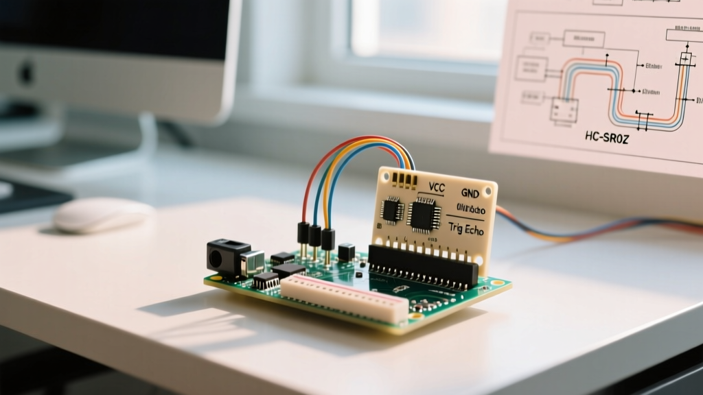
The module features a simple 4-pin interface: VCC, Trig, Echo, and GND. While wiring it to a 5V Arduino Uno is plug-and-play, interfacing it with modern 3.3V microcontrollers (like the ESP32, Raspberry Pi Pico RP2040, or Arduino Nano 33 IoT) requires a crucial extra step to prevent frying your board's GPIO pins.
| HC-SR04 Pin | Arduino Uno (5V Logic) | ESP32 / RP2040 (3.3V Logic) | Function |
|---|---|---|---|
| VCC | 5V Pin | 5V Pin (or VIN) | Powers the module (Requires 5V, will not work reliably on 3.3V) |
| Trig | Digital Pin 9 | GPIO 5 | Receives a 10µs HIGH pulse to initiate measurement |
| Echo | Digital Pin 10 | GPIO 18 (via Voltage Divider) | Outputs a HIGH pulse proportional to distance |
| GND | GND | GND | Common ground reference |
The 3.3V Logic Voltage Divider
The HC-SR04 Echo pin outputs a 5V HIGH signal when measuring distance. If you connect this directly to an ESP32 or RP2040, you risk permanently damaging the 3.3V-tolerant GPIO pin. You must use a voltage divider to step the 5V down to ~3.3V. Wire a 1kΩ resistor in series with the Echo pin, and connect a 2kΩ resistor from the junction point to GND. This safely drops the voltage to 3.33V.
Writing the Ultrasonic Sensor Arduino Code
There are two primary ways to write ultrasonic sensor Arduino code: using the raw, built-in pulseIn() function, or utilizing the highly optimized NewPing library. We will cover both, explaining why the latter is superior for complex projects.
Method 1: Raw pulseIn() Implementation (No Libraries)
The native Arduino pulseIn() function waits for a pin to go HIGH, starts counting microseconds, and stops when the pin goes LOW. This is great for simple sketches but blocks the main loop, meaning your microcontroller can do absolutely nothing else while waiting for an echo.
// Define Pins
const int trigPin = 9;
const int echoPin = 10;

// Variables for calculation
long duration;
float distanceCm;

void setup() {
  Serial.begin(9600);
  pinMode(trigPin, OUTPUT);
  pinMode(echoPin, INPUT);
}

void loop() {
  // 1. Clear the trigger pin
  digitalWrite(trigPin, LOW);
  delayMicroseconds(2);

  // 2. Set trigger HIGH for 10 microseconds
  digitalWrite(trigPin, HIGH);
  delayMicroseconds(10);
  digitalWrite(trigPin, LOW);

  // 3. Read the echo pin (returns time in microseconds)
  duration = pulseIn(echoPin, HIGH, 30000); // 30ms timeout prevents infinite hangs

  // 4. Calculate distance
  if (duration == 0) {
    Serial.println("Out of range or timeout!");
  } else {
    distanceCm = (duration * 0.0343) / 2.0;
    Serial.print("Distance: ");
    Serial.print(distanceCm);
    Serial.println(" cm");
  }

  delay(100); // Wait 100ms before next ping to avoid acoustic interference
}
Method 2: The NewPing Library (Recommended for 2026)
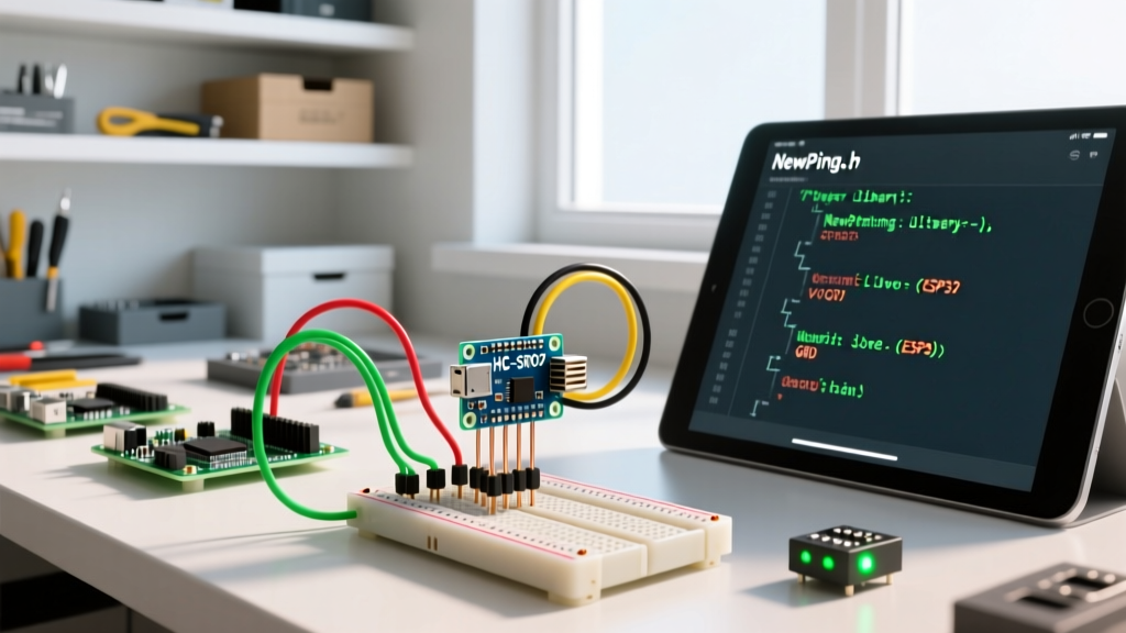
For any project involving motors, displays, or Wi-Fi, blocking code is unacceptable. The NewPing library by Tim Eckel is the industry standard for HC-SR04 integration. It features non-blocking timer-based pings, automatic median filtering to discard acoustic outliers, and built-in timeout handling.
#include <NewPing.h>

#define TRIGGER_PIN  9
#define ECHO_PIN     10
#define MAX_DISTANCE 400 // HC-SR04 max reliable range is ~400cm

// Initialize NewPing object
NewPing sonar(TRIGGER_PIN, ECHO_PIN, MAX_DISTANCE);

void setup() {
  Serial.begin(115200);
}

void loop() {
  // ping_cm() handles the timing and math automatically
  unsigned int distance = sonar.ping_cm();

  if (distance > 0) {
    Serial.print("Ping: ");
    Serial.print(distance);
    Serial.println(" cm");
  } else {
    Serial.println("No echo detected.");
  }

  delay(50); // NewPing recommends at least 35ms between pings
}
Sensor Comparison: Is the HC-SR04 Right for Your Project?
While the HC-SR04 is cheap, it is not always the correct tool for the job. Before finalizing your Bill of Materials (BOM), compare it against modern alternatives available on the market.
| Feature | HC-SR04 (Ultrasonic) | VL53L1X (Time-of-Flight Laser) | RCWL-0516 (Microwave Radar) |
|---|---|---|---|
| Technology | 40 kHz Sound Waves | Infrared Laser (ToF) | Doppler Microwave Radar |
| Typical Price (2026) | $1.50 - $3.00 | $6.00 - $9.00 | $2.00 - $4.00 |
| Blind Zone | ~2 cm | ~0 cm | N/A (Detects motion, not static distance) |
| Max Range | 400 cm | 400 cm (up to 800cm in dark) | 500 - 900 cm |
| Beam Angle | ~30° (Wide cone) | ~27° (Configurable ROI) | Omnidirectional / Through walls |
| Best Use Case | Tank level, basic robotics | Precision robotics, gesture control | Security alarms, human presence |
Real-World Troubleshooting and Edge Cases
When testing your ultrasonic sensor Arduino code on a breadboard, you will likely encounter erratic readings. Here is how domain experts troubleshoot the most common HC-SR04 failure modes.
1. Acoustic Multipath and Beam Angle Interference
The HC-SR04 has a beam angle of roughly 30 degrees (15 degrees off-center in all directions). If you mount the sensor too close to the floor or a side wall, the sound wave will bounce off the floor/wall before hitting your target object. This "multipath" effect results in phantom readings. Solution: Mount the sensor at least 15 cm above the ground and use physical shrouds (like a short PVC tube) around the receiver mesh to narrow the acoustic field of view.
2. Soft and Sound-Absorbing Materials
Ultrasonic sensors rely on a hard acoustic reflection. If your robot approaches a thick curtain, a foam mat, or a person wearing heavy winter clothing, the sound waves are absorbed rather than reflected. The Echo pin will time out, returning a 0 or maximum distance. Solution: Implement sensor fusion. Pair the HC-SR04 with an infrared ToF sensor (like the VL53L0X) to catch soft objects that absorb sound.
3. Acoustic Cross-Talk in Multi-Sensor Arrays
If you are building a robot with three or four HC-SR04 modules (e.g., front, left, right, rear), firing them simultaneously will cause cross-talk. Sensor A's receiver will pick up Sensor B's transmitter burst, resulting in wildly inaccurate short-distance readings. Solution: Never ping multiple HC-SR04 modules at the exact same time. Use the NewPing library's event-driven timer functions to ping each sensor sequentially, leaving at least 35-50 milliseconds between each ping to allow the acoustic energy to dissipate.
4. Power Supply Noise and Brownouts
The HC-SR04 draws a spike of current (up to 15mA) when the transmitter fires. If you are powering multiple sensors or servos from the same 5V rail, this spike can cause a voltage brownout, resetting your Arduino or corrupting the I2C bus. Solution: Place a 100µF electrolytic capacitor across the VCC and GND pins of the HC-SR04 to smooth out transient current spikes.
Summary
Writing reliable ultrasonic sensor Arduino code requires more than just copying a basic sketch. By understanding the 10µs trigger timing, applying the correct speed-of-sound math, utilizing the non-blocking NewPing library, and respecting the physical limitations of acoustic wave propagation, you can build robust, real-world distance measurement systems. Always remember to step down the 5V Echo signal when migrating from classic 5V Arduinos to modern 3.3V architectures like the ESP32 or RP2040.
For more advanced sensor integration guides, including I2C Time-of-Flight arrays and LiDAR mapping, explore our extensive Sensors & Peripherals knowledge hub.