
The HD44780 Ecosystem in 2026: Why the 16x2 LCD Endures
Despite the proliferation of cheap SPI OLEDs and IPS TFT screens, the LCD display Arduino 16x2 remains a cornerstone of embedded prototyping and industrial control panels. Based on the legendary Hitachi HD44780 controller, these modules offer unmatched readability in direct sunlight, extreme temperature tolerance (typically -20°C to 70°C for STN variants), and a rugged physical footprint. In 2026, a standard 1602A module costs between $3.50 and $5.00, while an I2C-equipped version retails for around $7.00.
This comprehensive wiring and code guide focuses on the I2C backpack method, which reduces the required microcontroller pins from six down to just two (SDA and SCL), freeing up critical GPIO for sensors and motor control peripherals.
Parallel vs. I2C Backpack: Engineering Trade-offs
Before wiring your LCD display Arduino 16x2, you must choose your interface. While 4-bit parallel is the native HD44780 protocol, the PCF8574 I2C port expander backpack is the modern standard for DIY and low-volume production.
| Feature | 4-Bit Parallel (Native) | I2C Backpack (PCF8574) |
|---|---|---|
| GPIO Pins Required | 6 (RS, EN, D4, D5, D6, D7) | 2 (SDA, SCL) |
| Wiring Complexity | High (requires 10kΩ contrast pot) | Low (integrated contrast pot) |
| Bus Speed / Refresh | Fast (~1.5 ms per command) | Slower (I2C overhead adds ~2-4 ms) |
| Power Consumption | Lower (no I2C expander quiescent current) | Slightly higher (+1-2 mA for PCF8574) |
| Best Use Case | High-speed data logging, battery-critical IoT | General UI, dashboards, pin-constrained MCUs |
Step-by-Step I2C Wiring Guide
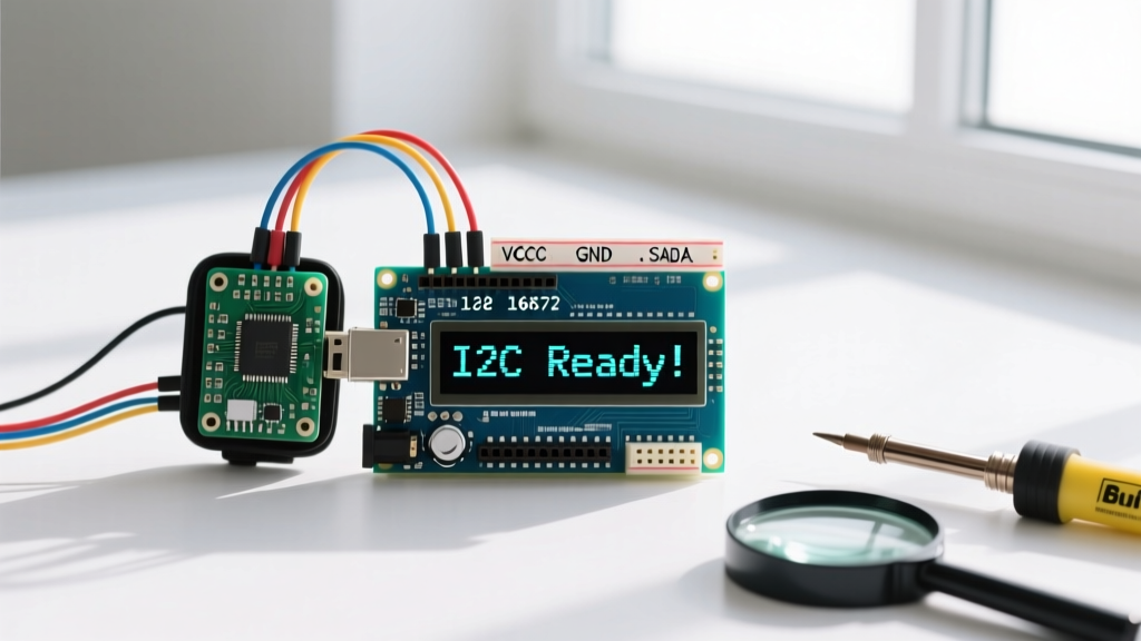
The I2C backpack uses a PCF8574 or PCF8574A I/O expander chip to translate I2C serial data into the parallel signals the HD44780 requires. Soldering the backpack to the 16-pin LCD header requires careful alignment; misaligning by one pin and applying power will instantly destroy the expander chip.
Arduino Uno / Nano Pinout
- VCC: 5V (Do not use 3.3V; the HD44780 logic and backlight require 4.5V minimum).
- GND: Common Ground.
- SDA: A4 (on Uno/Nano) or dedicated SDA pin.
- SCL: A5 (on Uno/Nano) or dedicated SCL pin.
ESP32 Pinout
- VCC: 5V (VIN pin).
- GND: GND.
- SDA: GPIO 21.
- SCL: GPIO 22.
Hardware Warning: The ESP32 operates at 3.3V logic. While the PCF8574 I2C lines are often tolerant of 3.3V pull-ups, if your specific backpack has 4.7kΩ pull-ups tied to 5V, you must use a bidirectional logic level shifter on the SDA/SCL lines to prevent long-term degradation of the ESP32 GPIO pads.
Finding the Correct I2C Address
The most common failure point when setting up an LCD display Arduino 16x2 is an incorrect I2C address. Manufacturers use two variants of the PCF8574 chip:
- PCF8574: Base address typically
0x27(can be altered via A0, A1, A2 jumper pads to range 0x20–0x27). - PCF8574A: Base address typically
0x3F(ranges 0x38–0x3F).
According to the NXP PCF8574 Datasheet, the 'A' variant shifts the address space to allow multiple identical peripherals on the same bus. Always run an I2C scanner sketch before writing your main application logic.
#include <Wire.h>

void setup() {
  Wire.begin();
  Serial.begin(115200);
  Serial.println("I2C Scanner Ready...");
}

void loop() {
  byte error, address;
  for(address = 1; address < 127; address++ ) {
    Wire.beginTransmission(address);
    error = Wire.endTransmission();
    if (error == 0) {
      Serial.print("LCD Found at 0x");
      Serial.println(address, HEX);
    }
  }
  delay(5000);
}
Core Code Implementation
To drive the display, install the LiquidCrystal_I2C library by Frank de Brabander via the Arduino Library Manager. This library abstracts the bit-banging required to toggle the Enable (E) and Register Select (RS) pins via the I2C expander.
#include <Wire.h>
#include <LiquidCrystal_I2C.h>

// Initialize with address 0x27, 16 columns, 2 rows
LiquidCrystal_I2C lcd(0x27, 16, 2);

void setup() {
  lcd.init();
  lcd.backlight(); // Turn on the LED backlight

  // Custom initialization sequence for stable boot
  lcd.clear();
  lcd.setCursor(0, 0);
  lcd.print("System Booting...");
  delay(1500);
  lcd.clear();
}

void loop() {
  // Print sensor data or status
  lcd.setCursor(0, 0);
  lcd.print("Temp: 24.5 C");
  lcd.setCursor(0, 1);
  lcd.print("Hum:  62 %");
  delay(1000);
}
Advanced: Custom Characters & CGRAM Mapping
The HD44780 controller features 64 bytes of Character Generator RAM (CGRAM), allowing you to define up to eight custom 5x8 pixel characters. This is heavily utilized in battery indicators, signal strength bars, and custom arrows. The Hitachi HD44780 Datasheet details the exact memory mapping for these slots (0x00 to 0x07).
Below is an example of creating a custom thermometer icon:
byte thermometer[8] = {
  B00100,
  B01010,
  B01010,
  B01010,
  B01110,
  B11111,
  B11111,
  B01110
};

void setup() {
  lcd.init();
  lcd.createChar(0, thermometer); // Store in slot 0
  lcd.setCursor(0,0);
  lcd.write((byte)0); // Print custom char
  lcd.print(" 24.5C");
}
Real-World Troubleshooting & Failure Modes
When your LCD display Arduino 16x2 fails to render correctly, avoid rewriting your code immediately. 90% of display issues are hardware or electrical in nature.
1. Solid Row of Black Boxes on Top Line
Cause: The LCD has power, but the contrast voltage (V0) is incorrect, or the initialization sequence failed. On I2C backpacks, there is a small blue trimpot.
Fix: Use a multimeter to measure the voltage on the V0 pin (pin 3 of the LCD). Adjust the trimpot until V0 reads between 0.4V and 0.7V. If the voltage is correct but boxes remain, the I2C address in your code is wrong, preventing the lcd.init() command from reaching the controller.
2. Backlight Flickering or Dim
Cause: The LED backlight array draws between 80mA and 150mA depending on the color (blue/white draw more than green). If powered directly from an Arduino Uno's 5V USB line, you may be exceeding the USB polyfuse limit (typically 500mA total for the board and all peripherals).
Fix: Power the LCD VCC line from a dedicated 5V buck converter or an external bench supply, tying the GND back to the Arduino. You can also disable the backlight in code using lcd.noBacklight() during idle states to save power.
3. Ghosting or Stuck Characters
Cause: I2C bus noise or missing pull-up resistors. While the PCF8574 backpack usually includes 4.7kΩ pull-ups to 5V, long wire runs (over 30cm) will cause signal degradation, resulting in corrupted bytes that print garbage characters.
Fix: Add external 2.2kΩ pull-up resistors on both SDA and SCL lines near the microcontroller, or reduce the I2C clock speed using Wire.setClock(100000); (100kHz standard mode) instead of the default 400kHz Fast mode.
Frequently Asked Questions
Can I use a 3.3V microcontroller like the Raspberry Pi Pico with this 16x2 LCD?
Yes, but you must power the LCD VCC with 5V for the backlight and logic to function correctly. Use a logic level shifter for the SDA/SCL lines to step the Pico's 3.3V I2C signals up to 5V, ensuring reliable communication with the PCF8574 backpack.
Why does my display show reversed text or mirrored characters?
This occurs if the RW (Read/Write) pin on the native HD44780 is left floating or pulled HIGH. On an I2C backpack, the RW pin is hardwired to GND by the manufacturer. If you are wiring in parallel mode without a backpack, you must tie the RW pin directly to GND to force the LCD into Write mode.
Is the LiquidCrystal_I2C library compatible with the official Arduino Cloud IoT?
Yes. The LiquidCrystal architecture is fully supported within the Arduino IoT Cloud environment. However, ensure you do not block the main loop with excessive delay() calls while updating the display, as this can cause cloud synchronization timeouts.