
The Reality of Acoustic Sensing in Microcontroller Projects
If you have ever tried to build a 'clap switch' or an ambient noise monitor using a generic sound sensor module Arduino tutorial, you likely ended up with a circuit that either triggers from a pin dropping on the floor or fails to register a loud handclap. The root cause is rarely the code; it is almost always a misunderstanding of the hardware's analog front-end and improper threshold calibration.
In this comprehensive integration guide, we move beyond basic digital readouts. We will dissect the anatomy of the ubiquitous KY-038 and KY-037 modules, establish a rigorous calibration protocol for the onboard LM393 comparator, and explore advanced analog sampling techniques required for actual audio processing in 2026.
Hardware Anatomy: KY-038 vs. KY-037
Most hobbyist sound sensors rely on an electret microphone capsule paired with a basic operational amplifier or comparator. The capsule contains a permanently charged dielectric material and an internal JFET (Junction Field-Effect Transistor) that acts as an impedance converter, requiring a bias voltage (typically 2V to 5V) to operate.
The amplified AC signal is then fed into an LM393 dual differential comparator, which checks the signal peak against a DC reference voltage set by a 10kΩ trimpot. If the audio peak exceeds the reference, the digital output (D0) pulls LOW.
Module Comparison Matrix
| Feature | KY-038 (Compact) | KY-037 (High-Sensitivity) |
|---|---|---|
| Capsule Size | ~6mm x 8mm | ~9mm x 12mm |
| Effective Range | 0.5m - 1.5m (Loud noises) | 1.0m - 3.0m (Moderate noises) |
| Board Dimensions | 32mm x 15mm | 45mm x 15mm |
| Typical 2026 Cost | ~$0.35 per unit (bulk) | ~$0.55 per unit (bulk) |
| Best Use Case | Proximity knock detection, impact sensing | Room occupancy, volume metering, voice triggers |
Precision Wiring and Pinout
While these modules operate from 3.3V to 5V, powering them from a noisy 5V USB rail often introduces high-frequency switching noise from the microcontroller's voltage regulator into the microphone's bias circuit. For the cleanest analog readings, power the module from a dedicated 3.3V LDO or use a ferrite bead on the VCC line.
Standard Arduino Uno R3 / Nano Wiring
- VCC: Connect to 3.3V or 5V (3.3V recommended for lower noise floor).
- GND: Connect to Arduino GND. Critical: Use a star-ground topology if you are also driving motors or relays to prevent ground bounce.
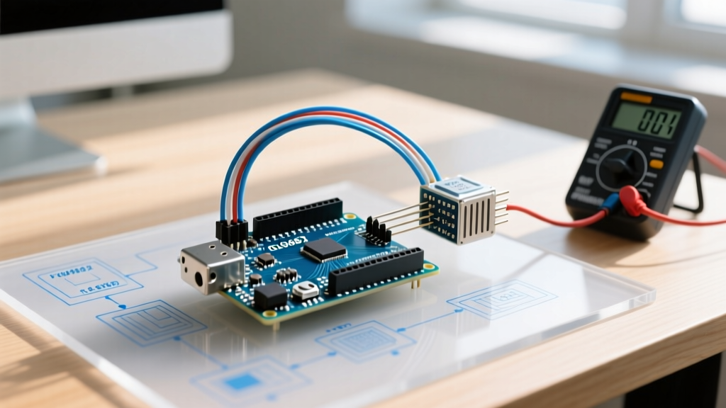
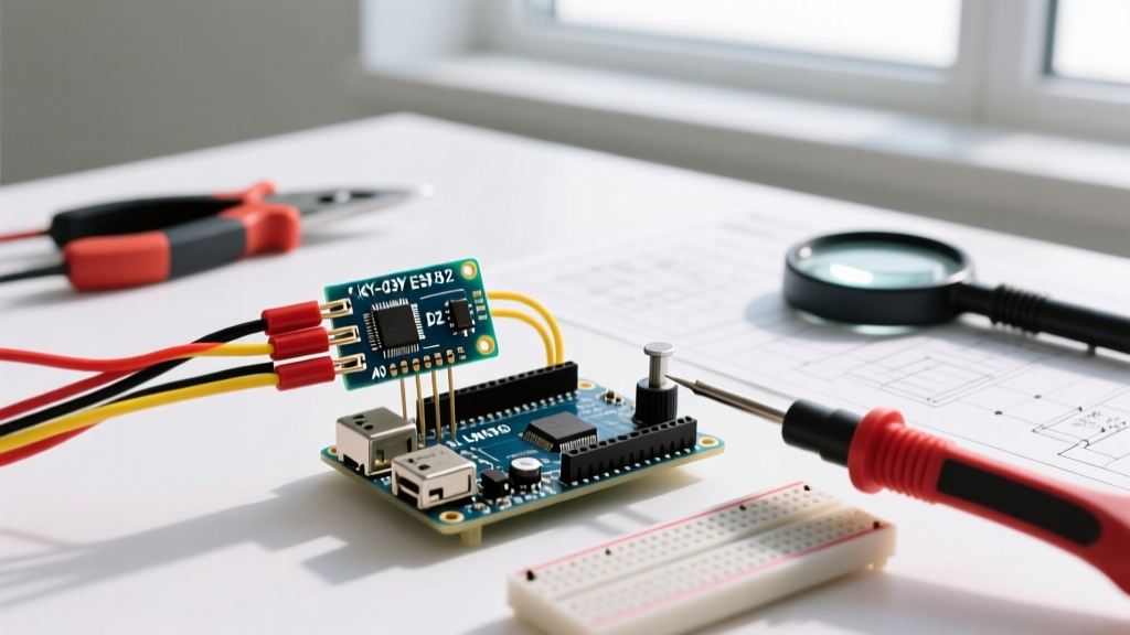
- D0 (Digital Out): Connect to Digital Pin 2 (for hardware interrupt support).
- A0 (Analog Out): Connect to Analog Pin A0.
The 'Screwdriver Protocol': Proper LM393 Calibration
The most common failure mode in sound sensor integration is an improperly tuned potentiometer. Turning it blindly will result in a digital output that is either permanently HIGH or permanently LOW. Follow this exact calibration sequence to set the threshold just above your ambient noise floor.
Pro-Tip: Do not attempt to calibrate the sensor in a dead-silent room if your final deployment will be in a living room or office. Calibrate the sensor in the actual acoustic environment where it will operate.
- Upload a blank sketch that simply reads Digital Pin 2 and prints the state to the Serial Monitor at 115200 baud.
- Power the module and observe the onboard LEDs. LED1 indicates power; LED2 indicates the comparator output state.
- Using a small flathead screwdriver, turn the blue trimpot clockwise slowly. You will see LED2 turn ON.
- Once LED2 is solidly ON, reverse direction and turn the pot counter-clockwise very slowly until LED2 turns OFF.
- Continue turning counter-clockwise by roughly 2 to 3 degrees (about 1/16th of a full rotation). This establishes a hysteresis buffer, ensuring that minor ambient fluctuations (like an HVAC system turning on) do not cause false digital triggers.
Arduino Code Implementation: Beyond Digital Reads
While the D0 pin is useful for simple knock detection, the A0 pin unlocks the module's true potential for volume metering and acoustic profiling. When using the analogRead() function, remember that the default Arduino ADC resolution is 10-bit (0-1023), mapping to 0V-5V.
Non-Blocking Envelope Follower Code
Audio signals are AC waveforms oscillating around a DC bias (usually ~2.5V on the A0 pin). To measure 'loudness', we must calculate the peak-to-peak deviation from this bias over a short sampling window.
const int micPin = A0;
const int sampleWindow = 50; // Sample window width in mS (50 mS = 20Hz)
unsigned long startMillis;
unsigned int peakToPeak;
unsigned int signalMax = 0;
unsigned int signalMin = 1024;

void setup() {
  Serial.begin(115200);
  startMillis = millis();
}

void loop() {
  unsigned long currentMillis = millis();
  if (currentMillis - startMillis < sampleWindow) {
    unsigned int sample = analogRead(micPin);
    if (sample < 1024) { // Sanity check
      if (sample > signalMax) signalMax = sample;
      if (sample < signalMin) signalMin = sample;
    }
  } else {
    peakToPeak = signalMax - signalMin;
    // Map to a relative volume percentage (adjust 400 based on your calibration)
    int volume = map(peakToPeak, 0, 400, 0, 100);
    volume = constrain(volume, 0, 100);
    Serial.print("Volume: ");
    Serial.println(volume);

    // Reset for next window
    startMillis = currentMillis;
    signalMax = 0;
    signalMin = 1024;
  }
}
Advanced Integration: Overcoming the ADC Sampling Bottleneck
If your project requires Fast Fourier Transform (FFT) analysis to identify specific frequencies (e.g., distinguishing a glass breaking from a dog barking), the default Arduino analog input configuration will fail you.
By default, the ATmega328P ADC clock is set to the system clock divided by 128 (16MHz / 128 = 125kHz). Because a single 10-bit conversion takes 13 ADC clocks, your maximum sampling rate is roughly 9.6kHz. According to the Nyquist-Shannon sampling theorem, this limits your maximum detectable frequency to ~4.8kHz, completely blinding you to higher-frequency acoustic transients.
The ADC Prescaler Hack
To achieve a sampling rate of ~19kHz to ~38kHz (sufficient for basic voice and glass-break detection), you must manipulate the ADCSRA (ADC Control and Status Register A) prescaler bits in your setup() function:
// Set ADC prescaler to 32 (16MHz / 32 = 500kHz ADC clock)
// Yields approx 38.4kHz sampling rate
bitClear(ADCSRA, ADPS0);
bitSet(ADCSRA, ADPS1);
bitSet(ADCSRA, ADPS2);
Warning: Increasing the ADC clock speed slightly reduces effective resolution (dropping from a true 10-bit to roughly 8.5-bit accuracy), but for AC audio envelope tracking, the speed trade-off is entirely worth it.
Real-World Failure Modes & Troubleshooting Matrix
Even with perfect code, environmental factors can ruin acoustic sensor performance. Use this matrix to diagnose erratic behavior in the field.
| Symptom | Probable Cause | Hardware / Software Fix |
|---|---|---|
| Constant 50/60Hz rhythmic triggering | Mains hum coupling into the high-impedance mic capsule. | Move sensor away from AC transformers; add a 100nF ceramic capacitor directly across the module's VCC and GND pins. |
| Analog values drift slowly over time | Temperature coefficient of the electret capsule's internal JFET. | Implement a software rolling-average high-pass filter to dynamically track and subtract the DC bias drift. |
| Digital pin triggers when motors spin | Ground bounce and voltage droop on shared power rails. | Isolate motor power; use optocouplers for digital signals; implement a 50ms software debounce on the D0 interrupt. |
| Sensor is completely deaf to loud noises | Electret capsule FET is biased incorrectly or damaged by ESD. | Check VCC voltage (must be >2.5V); replace the capsule if the LM393 non-inverting input reads a flat 0V. |
Final Deployment Considerations
When integrating a sound sensor module into a permanent 2026 IoT deployment, physical mounting is just as critical as electrical wiring. Mounting the KY-038 directly to a vibrating chassis (like a 3D printer or an HVAC duct) will cause structure-borne noise to completely overwhelm the acoustic capsule. Always use a silicone grommet or double-sided foam tape to acoustically decouple the sensor PCB from the mounting surface. By combining proper mechanical isolation, the screwdriver calibration protocol, and optimized ADC sampling, you can transform a $0.50 hobbyist component into a highly reliable industrial acoustic trigger.