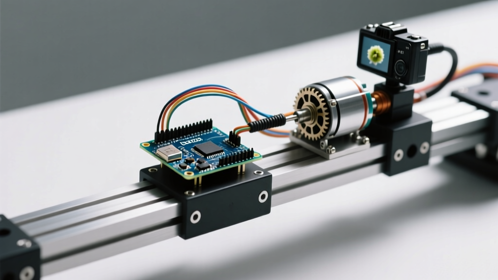

The Problem with Open-Loop Stepper Control
Stepper motors are the backbone of precision DIY automation, CNC routers, and 3D printers. However, a standard stepper motor with Arduino setup operates in an open-loop configuration. The microcontroller sends step pulses, blindly assuming the rotor has followed the magnetic field. If the mechanical load exceeds the motor's holding torque, or if an unexpected obstacle enters the travel path, the motor stalls or skips steps without the Arduino ever knowing.
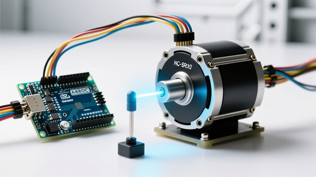
By integrating environmental sensors directly into the motor control loop, we transition from a blind actuator to a responsive, semi-closed-loop system. In this 2026 integration tutorial, we will wire a NEMA 17 stepper motor to an Arduino Uno R4 Minima, drive it via a DRV8825 IC, and use an HC-SR04 ultrasonic sensor to dynamically adjust speed and halt travel when an obstacle is detected within a 15cm threshold.
2026 Hardware BOM: Building the Sensor-Integrated Actuator
Supply chain stabilization in 2026 has made high-torque steppers and advanced microcontrollers more accessible. Below is the exact Bill of Materials required for this build, featuring the modern Arduino Uno R4 Minima, which utilizes a 48MHz Renesas RA4M1 ARM Cortex-M4 processor to handle non-blocking sensor polling and high-speed step generation simultaneously.
| Component | Specific Model | Est. 2026 Price | Engineering Purpose |
|---|---|---|---|
| Microcontroller | Arduino Uno R4 Minima | $28.00 | 48MHz processing for non-blocking sensor interrupts |
| Stepper Motor | NEMA 17 (17HS4401) | $14.50 | 1.5A/phase, 42Ncm holding torque, 1.8 deg step angle |
| Motor Driver | DRV8825 Breakout | $3.20 | 1/32 microstepping, up to 45V and 2.5A per phase |
| Proximity Sensor | HC-SR04 Ultrasonic | $2.50 | 40kHz acoustic transceiver, 2cm to 400cm range |
| Power Supply | 12V 3A Switching PSU | $9.00 | Provides clean DC for motor coils, preventing brownouts |
| Decoupling Caps | 100nF MLCC (0.1uF) | $0.10 | High-frequency EMI filtering for sensor VCC lines |
Wiring Matrix: Arduino, DRV8825, and HC-SR04
Proper isolation between the high-current motor coils and the low-voltage logic lines is critical. The DRV8825 handles the heavy lifting, while the Arduino R4 Minima acts purely as the logic controller. The HC-SR04 operates on 5V logic, which is natively supported by the Uno R4's 5V output pin.
| Arduino R4 Pin | Target Module | Module Pin | Wire Color (Standard) |
|---|---|---|---|
| D3 (PWM/Step) | DRV8825 | STEP | Green |
| D4 (Dir) | DRV8825 | DIR | Yellow |
| GND | DRV8825 | GND | Black |
| D6 (Trig) | HC-SR04 | Trig | Orange |
| D7 (Echo) | HC-SR04 | Echo | Brown |
| 5V | HC-SR04 | VCC | Red |
Note: The DRV8825 VMOT pin must be connected directly to the 12V PSU positive terminal, and the PSU ground must be tied to the Arduino GND to establish a common reference plane. Never power VMOT from the Arduino's onboard regulator.
Critical Setup: Tuning the DRV8825 Current Limit
The most common point of failure in DIY stepper projects is skipping the VREF tuning step. If the current limit is set too low, the motor will stall under load. If set too high, the 17HS4401 will overheat, and the DRV8825 will trigger its internal thermal shutdown.
Calculating VREF for the 17HS4401
According to Texas Instruments' DRV8825 datasheet, the current limit is defined by the voltage on the REF pin and the value of the sense resistors on the breakout board. Most modern 2026 DRV8825 carrier boards use 0.100Ω sense resistors.
The formula is: Current Limit = VREF × 2
Since our 17HS4401 motor is rated for 1.5A per phase, we calculate the target VREF:
- VREF = 1.5A / 2
- VREF = 0.75V
Using a digital multimeter, place the positive probe on the trimpot on the DRV8825 and the negative probe on the Arduino GND. Turn the trimpot with a ceramic screwdriver until you read exactly 0.75V. Do not use a metal screwdriver, as it can short the trimpot terminals to nearby logic traces.
Overcoming EMI: Sensor Shielding and Decoupling
Stepper motors generate massive Electromagnetic Interference (EMI) due to the rapid switching of high-current inductive coils. The HC-SR04 ultrasonic sensor is highly susceptible to this noise, which manifests as 'ghost readings' (e.g., the sensor reports 4cm when the path is clear, causing the motor to halt prematurely).
Expert Field Tip: Never route your HC-SR04 signal cables parallel to the stepper motor coil wires. If they must cross, force a 90-degree intersection. Furthermore, solder a 100nF MLCC ceramic capacitor directly across the VCC and GND pins on the back of the HC-SR04 PCB. This acts as a localized high-frequency filter, stabilizing the 5V rail against inductive kickback noise.
Non-Blocking Code Architecture
When integrating a stepper motor with Arduino, the code architecture is just as vital as the wiring. Standard stepper tutorials use the delay() function or basic for loops to generate steps. This completely fails when sensor feedback is introduced.
Why standard ping functions destroy stepper timing
The standard Arduino ping() or pulseIn() functions are blocking. They pause the entire microcontroller while waiting for the ultrasonic echo to return. At a maximum range of 400cm, the sound wave takes roughly 23 milliseconds to travel out and back.
If your stepper is moving at 1000 steps per second, a 23ms blocking delay means the Arduino will miss 23 consecutive step pulses. The motor will violently shudder, lose its position, and potentially stall. As detailed in Pololu's comprehensive stepper motor guide, maintaining strict, uninterrupted step timing is mandatory for rotor synchronization.
The Solution: Use the AccelStepper library combined with the NewPing library. AccelStepper uses hardware timers to generate step pulses in the background, while NewPing utilizes pin-change interrupts to listen for the ultrasonic echo without halting the main loop(). This ensures the motor continues to receive its 1000 steps per second while the sensor simultaneously maps the environment.
Real-World Troubleshooting Matrix
Even with perfect wiring, environmental factors can disrupt sensor-integrated actuators. Use this diagnostic matrix to resolve edge cases encountered in the field.
| Symptom | Root Cause Analysis | Engineering Fix |
|---|---|---|
| Motor hums but shaft does not turn at startup | Step frequency exceeds the motor's pull-in torque curve. | Implement an acceleration profile in AccelStepper. Set setMaxSpeed(800) and setAcceleration(400) to ramp up gradually. |
| HC-SR04 outputs random '0cm' or '2cm' readings | Acoustic reflections off the motor chassis or EMI noise on the Echo line. | Mount the sensor at least 5cm away from the motor body. Add a 100nF decoupling capacitor and enable NewPing's median filter (take 5 pings, discard outliers). |
| Motor runs hot (>60°C) and driver shuts down | VREF set too high, or lack of active cooling on the DRV8825. | Re-verify VREF at 0.75V. Apply a thermal pad and an aluminum heatsink to the DRV8825 IC, ensuring the fan blows directly across the fins. |
| Position drift over long travel distances | Missed steps due to mechanical resonance at specific RPMs. | Enable 1/16 or 1/32 microstepping on the DRV8825 (set MS1, MS2, MS3 pins HIGH). This smooths the magnetic vector and eliminates mid-range resonance bands. |
By respecting the physics of inductive loads and the timing constraints of acoustic sensors, you can elevate a basic hobby project into a robust, industrially viable actuator system.