
Beyond the Default Map Function: The Reality of Soil Moisture
If you have ever copied a basic tutorial for a soil humidity sensor Arduino project, you are likely using the map(val, 0, 1023, 100, 0) function to calculate moisture percentage. In professional agronomy and precision greenhouse automation, this approach is considered fundamentally flawed. Soil moisture is not a linear electrical property; it is a complex interaction of dielectric permittivity, ionic conductivity, and soil bulk density.
To achieve true accuracy in 2026, DIYers and embedded engineers must move past arbitrary analog thresholds and implement gravimetric calibration protocols. This guide details the exact hardware selection, ADC non-linearity corrections, and physical calibration steps required to transform a basic microcontroller setup into a precision agricultural tool.
Sensor Selection Matrix: Resistive vs. Capacitive vs. FDR
Before calibrating, you must understand the physical limitations of your sensor hardware. The market is flooded with cheap modules, but their long-term accuracy varies wildly.
| Sensor Model | Technology | Approx. Price (2026) | Lifespan in Soil | Interface |
|---|---|---|---|---|
| Generic YL-69 | Resistive | $1.50 | 1-3 Weeks | Analog (Voltage Divider) |
| Capacitive v1.2 | Capacitive (555 Timer) | $2.50 | 6-12 Months | Analog (Voltage) |
| Adafruit STEMMA (ID 4026) | Capacitive (I2C) | $7.50 | 2+ Years | I2C (Digital) |
| Vegetronix VH400 | FDR / TDR Hybrid | $49.95 | 5+ Years | Analog (Voltage) |
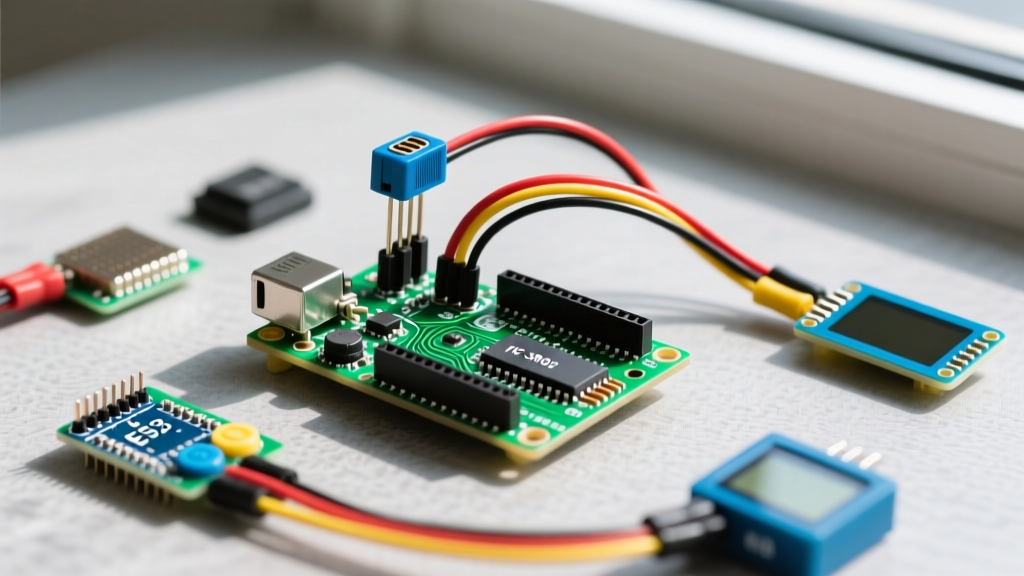
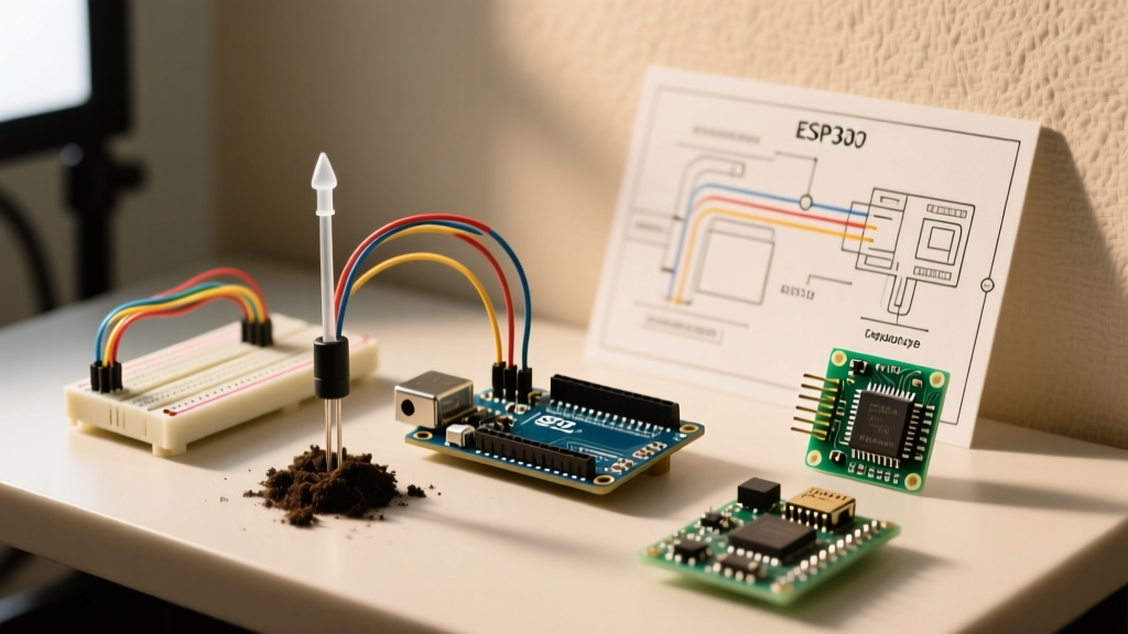
Expert Recommendation: For serious soil humidity sensor Arduino integrations, abandon resistive sensors immediately. The galvanic corrosion caused by passing direct current through damp soil will destroy the YL-69 probes in a matter of weeks, continuously shifting your baseline resistance and rendering calibration useless. The Adafruit STEMMA Soil Sensor is the current gold standard for DIYers, utilizing an I2C interface that completely bypasses the microcontroller's flawed internal ADC.
The ADC Bottleneck: Why Your Readings Are Drifting
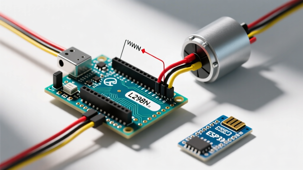
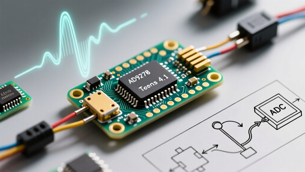
If you are using an analog sensor (like the Capacitive v1.2 or VH400) with an Arduino Uno (ATmega328P) or an ESP32, the microcontroller's Analog-to-Digital Converter (ADC) is often the primary source of inaccuracy.
Arduino Uno (ATmega328P) Reference Voltage Drift
By default, the Arduino Uno uses the 5V USB rail as the ADC reference. USB power from standard wall adapters frequently fluctuates between 4.7V and 5.2V. A 0.2V drop in reference voltage will skew your moisture reading by up to 4%. The Fix: Use the internal 1.1V reference by calling analogReference(INTERNAL); in your setup, and use a voltage divider to step the sensor output down to the 0-1.1V range.
ESP32 ADC Non-Linearity
The ESP32 is notorious for its non-linear ADC, particularly at the extremes of the 0-3.3V range. According to the official Espressif ADC documentation, the ADC attenuates signals non-linearly above 2.5V. If your capacitive sensor outputs 3.0V in completely dry soil, the ESP32 will compress those readings, destroying your dry-baseline calibration. Always configure your ESP32 ADC attenuation to 11dB and restrict your sensor's voltage output to the 0.15V - 2.4V linear sweet spot using a hardware voltage divider.
The 3-Point Gravimetric Calibration Protocol
To map voltage to actual Volumetric Water Content (VWC), you must perform a physical calibration using the soil you intend to monitor. As noted by Michigan State University Extension, soil texture (sand, silt, clay ratios) drastically alters the dielectric constant, meaning a factory calibration for potting soil will fail in dense garden clay.
- Prepare the Air-Dry Baseline (Point 1): Take a representative sample of your target soil and let it air-dry completely on a baking sheet for 48 hours. Insert the sensor and record the raw ADC value (e.g., 850 on a 10-bit scale). This represents ~5% VWC (hygroscopic water that cannot be removed by air drying).
- Achieve Field Capacity (Point 2): Place the soil in a pot with drainage holes. Saturate it completely with water, then let it drain freely for exactly 2 hours. This state is known as 'Field Capacity'. Insert the sensor and record the value (e.g., 420). For most loamy soils, this represents roughly 30-35% VWC.
- Establish Saturation (Point 3): Submerge the soil sample in a sealed container with a 1:1 soil-to-water ratio, creating a mud slurry. Insert the sensor and record the maximum saturation value (e.g., 210). This represents 100% saturation.
Calibration Math: Do not use a linear map between Point 1 and Point 3. Soil moisture response curves are exponential. Use a polynomial regression (2nd degree) in your Arduino code to map the ADC values to VWC percentages based on your three recorded data points.
Signal Conditioning: Hardware and Software Filtering
Soil environments are electrically noisy. Pump motors, LED grow lights, and Wi-Fi antennas introduce high-frequency interference that causes analog readings to jitter by 10-20 points.
Hardware RC Low-Pass Filter
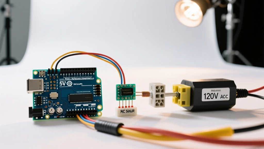
Solder a simple RC filter directly at the sensor's analog output pin before the wire runs to the Arduino. Use a 10kΩ resistor in series with the signal line, and a 100nF ceramic capacitor from the signal line to ground. This creates a cutoff frequency of roughly 159Hz, eliminating high-frequency EMI from switching power supplies.
Software Oversampling and Trimming
Never rely on a single analogRead(). Implement a software trimming algorithm that takes 16 rapid samples, discards the top 4 and bottom 4 outliers, and averages the remaining 8. This effectively increases your ADC resolution and eliminates transient noise spikes.
Long-Term Failure Modes and Edge Cases
Even with perfect initial calibration, environmental factors will degrade accuracy over time. Anticipate these specific failure modes in your system design:
- Fertilizer Salt Buildup: Capacitive sensors measure the dielectric permittivity of the soil. While they are immune to galvanic corrosion, high concentrations of dissolved ionic salts (from liquid fertilizers) can alter the soil's electrical conductivity, slightly skewing the capacitive field. Flush your soil with distilled water every 4 weeks to reset the ionic baseline.
- Temperature Drift: The dielectric constant of water changes with temperature. A sensor calibrated at 20°C (68°F) will read artificially 'drier' when the soil drops to 10°C (50°F). For high-precision setups, integrate a DS18B20 waterproof temperature probe and apply a temperature compensation coefficient of roughly +0.15% VWC per degree Celsius drop.
- Soil Compaction Voids: If the soil pulls away from the sensor probe during dry cycles (common in high-clay soils), the air gap acts as a dielectric insulator, causing the sensor to read 0% moisture even if the surrounding soil is damp. Use a probe with a tapered, wedge-like geometry to maintain physical soil contact during shrink-swell cycles.
Summary
Building a reliable soil humidity sensor Arduino system requires treating the soil as a complex chemical matrix rather than a simple resistor. By upgrading to I2C capacitive hardware, correcting for microcontroller ADC non-linearity, and performing a site-specific 3-point gravimetric calibration, you can achieve commercial-grade precision for a fraction of the cost of industrial TDR systems.