
The Physics of PPG: How Optical Heart Rate Sensors Work
Before writing a single line of code, it is critical to understand the underlying mechanism of your hardware. The heart rate sensor Arduino ecosystem is dominated by Photoplethysmography (PPG) modules. Unlike ECG sensors that measure electrical impulses via chest straps, PPG sensors use light to measure blood volume changes in the microvascular bed of tissue.
The Maxim Integrated (now Analog Devices) MAX30102 achieves this by pulsing two specific wavelengths of light into the skin:
- Red Light (660nm): Highly absorbed by oxygenated hemoglobin.
- Infrared Light (880nm): Passes through oxygenated blood but is absorbed by deoxygenated hemoglobin.
By calculating the ratio of light reflected back to the onboard photodetector, the sensor isolates the AC component (the pulsatile arterial blood volume) from the DC component (static tissue, venous blood, and ambient light). This AC waveform is then processed to extract Beats Per Minute (BPM).
Hardware Selection: Which Module Should You Buy?
Walking into the sensor aisle in 2026, you will generally encounter three distinct hardware tiers for heart rate monitoring. Choosing the wrong one is the number one reason beginners abandon their projects.
| Module Type | Core IC | Interface | Logic Level | Avg. Price (2026) | Best For |
|---|---|---|---|---|---|
| Generic MAX30102 Breakout | MAX30102 | I2C | 3.3V Strict | $4.50 - $7.00 | Budget projects, custom PCBs |
| SparkFun MAX30105 | MAX30105 | I2C | 5V Tolerant | $29.95 | Beginners, rapid prototyping |
| Pulse Sensor Amped | APDS-9008 | Analog | 5V Native | $24.99 | Simple analog-read projects |
Expert Recommendation: If you are using a 5V Arduino Uno R3, the generic $5 MAX30102 modules will require external logic level shifters and pull-up resistors. If you want a plug-and-play experience, invest in the SparkFun MAX30105 Breakout, which includes onboard voltage regulation and I2C pull-ups.
Bill of Materials & Wiring the I2C Bus
For this tutorial, we are assuming the use of an Arduino Uno R4 WiFi ($27.50) paired with a generic MAX30102 module to teach you the raw hardware realities of I2C interfacing.
The 3.3V vs 5V Logic Trap
The MAX30102 operates strictly at 3.3V. Feeding 5V into the VCC pin will instantly fry the internal LED drivers. Furthermore, the I2C data lines (SDA and SCL) are not 5V tolerant. While the Arduino Uno R4 features native 3.3V I2C pins, older Uno R3 boards output 5V on A4/A5, which can degrade the MAX30102 over time.
Pinout Configuration
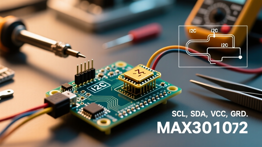
- VIN / VCC: Connect to Arduino 3.3V output.
- GND: Connect to Arduino GND.
- SDA: Connect to Arduino SDA (A4 on Uno R3, dedicated SDA pin on Uno R4).
- SCL: Connect to Arduino SCL (A5 on Uno R3, dedicated SCL pin on Uno R4).
- INT: (Optional) Connect to Digital Pin 2 for hardware interrupt-driven FIFO reading.
Critical Hardware Note: The I2C bus requires pull-up resistors to function. The Arduino Wire Library enables internal pull-ups, but they are often too weak (20kΩ - 50kΩ) for high-speed sensor communication. If your generic MAX30102 module lacks onboard 4.7kΩ resistors, you must solder 4.7kΩ resistors between the SDA/SCL lines and the 3.3V rail.
Firmware: Configuring the SparkFun Library
Do not attempt to write raw I2C register maps for your first project. The MAX30102 FIFO buffer and LED pulse amplitude registers are notoriously unforgiving. We will use the industry-standard SparkFun MAX3010x library, which is fully compatible with the MAX30102.
Install the "SparkFun MAX3010x Pulse and Proximity Sensor Library" via the Arduino IDE Library Manager. Below is the optimized initialization sequence for accurate BPM extraction:
#include <Wire.h>
#include "MAX30105.h"
#include "heartRate.h"

MAX30105 particleSensor;

const byte RATE_SIZE = 4;
byte rates[RATE_SIZE];
byte rateSpot = 0;
long lastBeat = 0;
float beatsPerMinute;
int beatAvg;

void setup() {
  Serial.begin(115200);
  Wire.begin();
  Wire.setClock(400000); // 400kHz I2C speed required for FIFO

  if (!particleSensor.begin(Wire, I2C_SPEED_FAST)) {
    Serial.println("MAX30102 not found. Check wiring and I2C pull-ups!");
    while (1);
  }

  // Advanced Configuration for Human Heart Rate
  particleSensor.setup(0x1F, 4, 2, 400, 411, 4096);
}
Decoding the setup() Parameters
Beginners often copy-paste the setup() function without understanding the physics implications. Here is what those arguments actually mean:
- 0x1F (LED Pulse Amplitude): Sets the IR LED current to roughly 7.6mA. If your readings are flat, increase this to
0x2F. If the sensor saturates (reads max 32767), decrease it. - 400 (Sample Rate): 400 samples per second. Lowering this to 100 saves power but reduces the resolution of the BPM peak-detection algorithm.
- 411 (Pulse Width): 411 microseconds. This dictates the ADC resolution (18-bit). Shorter widths yield lower resolution.
Real-World Troubleshooting & Edge Cases
Optical heart rate monitoring is highly susceptible to environmental noise. When your heart rate sensor Arduino build fails, it is rarely a code issue; it is almost always a physical interface problem.
Failure Mode 1: "Sensor Not Found" on I2C Bus
Symptom: The serial monitor prints the initialization failure message, and an I2C scanner sketch returns no devices at address 0x57.
The Fix: 90% of the time, this is a missing pull-up resistor issue. Grab a multimeter and measure the voltage on the SDA and SCL lines while the Arduino is powered. They should read a steady 3.3V. If they read 0V or float erratically, solder 4.7kΩ pull-up resistors to the 3.3V line. Additionally, verify that the generic module's LDO (Low Dropout Regulator) hasn't failed due to an accidental 5V connection.
Failure Mode 2: Erratic BPM Spikes (150 - 220 BPM)
Symptom: The sensor detects a beat, but the calculated BPM jumps wildly, even when your finger is resting.
The Fix: You are experiencing motion artifacts and capillary bed compression. The MAX30102 lacks an onboard accelerometer to cancel out motion (unlike advanced smartwatch chips).
Actionable Steps:
1. Rest your hand flat on a table; do not hold it in mid-air.
2. Apply gentle pressure. Pressing too hard compresses the capillaries, cutting off the pulsatile blood flow and leaving only the DC tissue reflection.
3. Block ambient light. The 60Hz/120Hz flicker from LED room lighting can bleed into the photodetector. Cover the sensor and your finger with a dark cloth during testing.
Failure Mode 3: FIFO Overflow Errors
Symptom: The serial monitor occasionally prints "FIFO Overflow" and skips beats.
The Fix: The MAX30102 features an internal 32-sample FIFO buffer. If your Arduino code spends too much time executing delay() functions or driving heavy displays (like an SPI TFT screen) inside the loop(), the buffer overwrites itself before the I2C bus can read it. Remove all blocking delays and use the INT pin to trigger an interrupt service routine (ISR) that reads the FIFO only when new data is ready.
References & Further Reading
To deepen your understanding of the MAX30102 architecture and I2C bus physics, consult the following authoritative documentation:
- Analog Devices MAX30102 Product Page & Datasheet - Essential reading for understanding the internal LED driver registers and optical isolation specifications.
- SparkFun MAX30105 Hookup Guide - The definitive guide on managing I2C logic levels and utilizing the SparkFun Arduino library for peak detection.
- Arduino Wire Library Reference - Official documentation on managing I2C bus speeds, pull-up configurations, and buffer limitations.