
The Hidden Cost of Uncalibrated Feedback
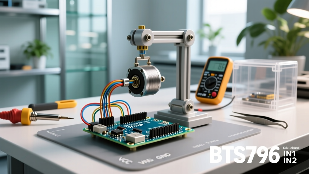
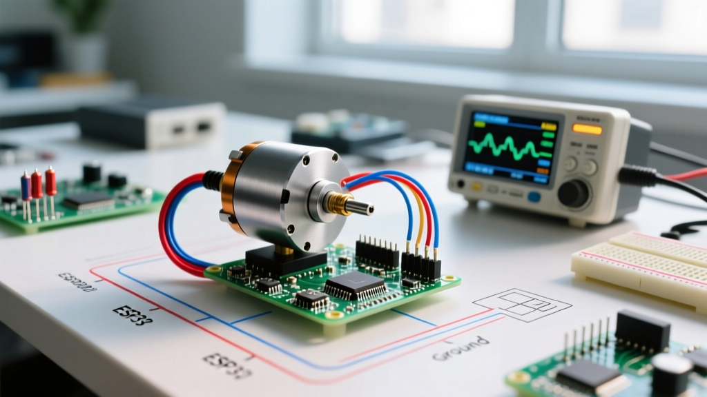
Integrating a dc motor with encoder arduino setups is the foundational step for closed-loop robotics, CNC machines, and automated guided vehicles (AGVs). However, simply reading pulse counts is not enough. Without rigorous calibration, mechanical backlash, electrical noise, and improper PID tuning will result in velocity ripple, positional overshoot, and system instability. In 2026, with the proliferation of high-torque brushless and brushed coreless motors, achieving sub-degree positional accuracy requires a systematic approach to hardware selection, signal conditioning, and algorithmic tuning.
This guide bypasses basic wiring tutorials and dives directly into the engineering realities of calibrating encoder feedback loops, ensuring your microcontroller translates raw quadrature pulses into precise mechanical motion.
Hardware Matrix: Selecting the Right Encoder Pairing
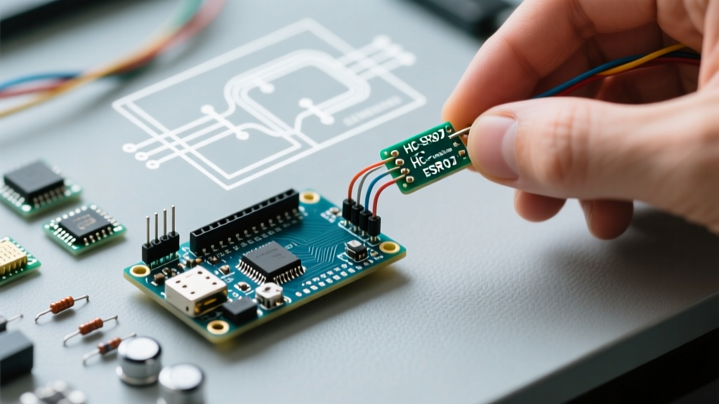
The accuracy of your closed-loop system is physically bottlenecked by the encoder's resolution and its susceptibility to environmental factors. As of 2026, the market offers distinct tiers of encoders. Beware of counterfeit magnetic sensors on open marketplaces; always source genuine components from authorized distributors like Mouser or DigiKey to ensure datasheet-level linearity.
| Encoder Type | Model Example | Resolution (CPR) | Interface | Avg Price (2026) | Best Application |
|---|---|---|---|---|---|
| Optical Quadrature | US Digital E4T | 256 - 1024 | Quadrature (A/B) | $65.00 | High-precision CNC, robotics |
| Magnetic (Hall Array) | Pololu 11-bit Magnetic | 2048 | I2C / SPI | $15.50 | Robotic arms, heavy-load rovers |
| Magnetic (Potentiometric) | AMS AS5600 (Genuine) | 4096 | I2C / Analog | $3.50 | Budget gimbals, low-speed joints |
| Integrated Gearmotor | Pololu 30:1 37Dx57L | 64 (Motor Shaft) | Quadrature (A/B) | $42.00 | Differential drives, AGVs |
Electrical Isolation and Noise Mitigation
DC motors are notorious EMI (Electromagnetic Interference) generators. The carbon brushes create high-frequency voltage spikes that travel through the power rails and corrupt the sensitive 3.3V/5V logic lines of your encoder. If you are experiencing erratic tick counts or phantom interrupts, your issue is almost certainly electrical, not software-related.
Mandatory Hardware Filtering
- Motor Terminal Capacitors: Solder a 0.1µF X7R ceramic capacitor directly across the motor terminals. Add two additional 0.1µF capacitors from each terminal to the motor's metal casing (ground).
- Logic Signal RC Filters: For quadrature encoders running cables longer than 15cm, implement a hardware low-pass RC filter on the A and B channels. A 1kΩ series resistor paired with a 1nF capacitor to ground creates a cutoff frequency of ~159kHz, effectively killing EMI spikes without degrading a 20kHz quadrature signal.
- Schmitt Triggers: If using long cable runs (>50cm), buffer the encoder signals through a 74HC14 hex Schmitt trigger IC before feeding them into the Arduino's digital pins to restore sharp rising/falling edges.
Pro-Tip on Grounding: Never share a ground return path between the motor power supply and the Arduino logic. Use a star-ground topology where the battery negative, motor driver ground, and Arduino ground meet at a single physical point to prevent ground loops.
The Mathematics of Quadrature Decoding
To calibrate a dc motor with encoder arduino systems, you must calculate the exact Ticks Per Revolution (TPR) at the output shaft. Integrated gearmotors, like the popular Pololu 30:1 metal gearmotor, report CPR (Counts Per Revolution) at the motor shaft, not the output shaft.
Calculation Framework:
- Base CPR: 64 (from the magnetic disc on the motor shaft).
- Gear Ratio: 30:1 (actual ratio is often 29.86:1 due to planetary gear tooth counts. Always verify the exact decimal ratio from the manufacturer's datasheet for high-precision applications).
- Shaft CPR: 64 × 29.86 = 1,911.04 counts per output revolution.
- Quadrature Decoding: By reading both rising and falling edges of both channels (4x decoding), you multiply the Shaft CPR by 4.
- Final TPR: 1,911.04 × 4 = 7,644.16 ticks per output revolution.
At a target speed of 100 RPM, your microcontroller must process 12,740 interrupts per second. Utilizing the highly optimized PJRC Encoder Library is mandatory here, as standard `attachInterrupt()` routines in the Arduino IDE will consume too much CPU overhead and drop ticks at these frequencies.
PID Calibration: The Modified Ziegler-Nichols Method
Translating tick velocity into smooth PWM output requires a PID (Proportional-Integral-Derivative) controller. While the Arduino Playground PID Library handles the math, tuning the constants (Kp, Ki, Kd) is where most projects fail. Do not guess your PID values. Use this systematic calibration protocol:
Step 1: Isolate Proportional Gain (Kp)
Set Ki = 0 and Kd = 0. Command a step change in velocity (e.g., 50 RPM). Gradually increase Kp until the motor begins to oscillate (audible humming or rhythmic speed surging). Note this critical gain as Ku (Ultimate Gain) and measure the time between oscillation peaks as Pu (Ultimate Period).
Step 2: Calculate Baseline Constants
Apply the Ziegler-Nichols formulas for a PI controller (Derivative is often detrimental in noisy mechanical systems):
- Kp = 0.45 × Ku
- Ki = (1.2 × Kp) / Pu
- Kd = 0 (Leave disabled unless dealing with high-inertia loads)
Step 3: Implement Anti-Windup Clamping
When a motor stalls or hits a hard limit, the Integral term accumulates massive error (Integral Windup), causing the motor to violently overshoot once the obstruction is cleared. In your Arduino code, strictly clamp the I-term accumulation to ±20% of your maximum PWM output (e.g., ±51 on a 0-255 scale).
Real-World Failure Modes and Edge Cases
Even with perfect math, physical realities introduce edge cases that break calibration. Consult this troubleshooting matrix when your system behaves unpredictably:
| Symptom | Root Cause | Engineering Solution |
|---|---|---|
| Motor jitters at zero velocity | Encoder noise causing micro-oscillations in the D-term. | Implement a software deadband (ignore errors < 5 ticks) or apply a low-pass filter to the derivative calculation. |
| Positional drift over time | Missed interrupts due to CPU blocking (e.g., I2C display updates). | Move all blocking code to a secondary core (ESP32) or use hardware timers. Never use `delay()` in a PID loop. |
| Non-linear response at low speeds | Static friction (Stiction) overcoming motor torque. | Implement 'Kickstart' logic: if error > 0 but velocity = 0, inject a 50ms burst of 30% PWM to break stiction before handing control back to PID. |
| I2C Encoder (AS5600) drops out | Bus capacitance from long wires or EMI from PWM lines. | Reduce I2C clock speed to 100kHz, add 2.2kΩ pull-up resistors to 3.3V, and physically separate I2C cables from motor phase wires. |
Sourcing and Final Integration
When sourcing Pololu Gearmotors and Encoders or similar high-precision assemblies, always request the batch-specific gear ratio tolerance if your application requires sub-millimeter linear positioning. In 2026, the integration of smart motor drivers (like the TI DRV8701) that feature hardware-based current limiting and built-in quadrature decoders can offload much of this processing from the Arduino, allowing your MCU to focus purely on high-level trajectory planning. By respecting the physics of your hardware and applying rigorous signal conditioning, your DC motor setup will achieve industrial-grade reliability.