
Why Treat an Arduino Display Touch Screen as a Sensor?
Most hobbyists view an arduino display touch screen purely as an output peripheral—a way to render text or graphics. However, from an integration perspective, the touch overlay is a complex, two-dimensional analog sensor. When you combine a resistive or capacitive touch matrix with environmental sensors (like a BME280 or SCD41), the microcontroller must simultaneously manage high-speed SPI data rendering, analog-to-digital touch sampling, and I2C sensor polling without dropping frames or blocking the main loop.
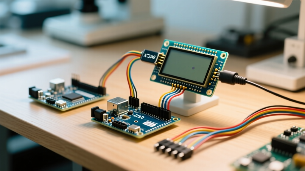
In this tutorial, we will integrate a 2.8-inch ILI9341 TFT LCD with an XPT2046 resistive touch controller into an Arduino Mega 2560 ecosystem. We will map raw ADC touch coordinates to screen pixels, resolve SPI bus contention, and build a non-blocking dashboard that reads and displays live temperature and humidity data.
Hardware Selection: Raw SPI vs. UART Smart Displays
Before wiring, it is critical to select the right architecture for your 2026 project requirements. The market currently offers two dominant paradigms for DIY touch interfaces:
| Feature | ILI9341 + XPT2046 (Raw SPI) | Nextion HMI (UART Smart Display) | Elecrow CrowPanel (ESP32 Integrated) |
|---|---|---|---|
| Interface | SPI (Display) + SPI (Touch) | Hardware Serial (UART) | Internal SPI / I2C |
| MCU Load | High (MCU renders all pixels) | Low (Onboard MCU handles UI) | Medium (ESP32 handles both) |
| Avg. Cost (2026) | $12 - $16 | $28 - $35 | $45 - $60 |
| Best Use Case | Custom sensor dashboards, low-budget | Complex HMI, industrial enclosures | IoT connected smart home panels |
For pure Arduino integration where you need direct, low-latency access to touch coordinates to trigger specific sensor calibration routines, the raw SPI arduino display touch screen (ILI9341 + XPT2046) remains the most flexible and cost-effective choice.
Pinout and SPI Bus Contention
The most common point of failure when wiring an Arduino display touch screen is SPI bus contention. Both the ILI9341 display controller and the XPT2046 touch controller use the SPI protocol. They can share the MOSI, MISO, and SCK lines, but they must have separate Chip Select (CS) pins and separate Interrupt/Data Command (DC) routing.
Arduino Mega 2560 Wiring Matrix
According to the official Arduino SPI documentation, the Mega 2560 routes its hardware SPI to pins 50 (MISO), 51 (MOSI), and 52 (SCK). Pin 53 is the default hardware SS, but we will use software-defined CS pins to manage the two SPI devices independently.
| ILI9341 / XPT2046 Pin | Arduino Mega 2560 Pin | Function & Notes |
|---|---|---|
| VCC | 5V | Module has onboard 3.3V LDO regulator |
| GND | GND | Common ground required for I2C sensors |
| CS (Display) | Pin 47 | Display Chip Select (Active LOW) |
| CS (Touch) | Pin 45 | Touch Chip Select (Active LOW) |
| RESET | Pin 43 | Hardware reset for ILI9341 |
| DC/RS | Pin 41 | Data/Command selector for Display |
| SDI(MOSI) | Pin 51 | Shared SPI Master Out Slave In |
| SDO(MISO) | Pin 50 | Shared SPI Master In Slave Out |
| SCK | Pin 52 | Shared SPI Clock |
| IRQ | Pin 2 | Touch Interrupt (Must be hardware INT pin) |
Expert Warning: Never tie the Display CS and Touch CS pins together. If both chips are selected simultaneously, they will both attempt to drive the MISO line, resulting in data corruption, a white screen, or permanent damage to the module's logic buffers.
The Calibration Matrix: Mapping Raw ADC Data
The XPT2046 is a 4-wire resistive touch controller. When you press the screen, it measures voltage drops across the X and Y layers, returning raw 12-bit ADC values (typically ranging from 200 to 3900). These raw values do not map 1:1 with the 320x240 pixel grid of the ILI9341 display.
To build a reliable arduino display touch screen interface, you must implement a calibration matrix. Using Paul Stoffregen's highly optimized XPT2046_Touchscreen library, we read the raw coordinates and map them to screen space.
Calibration Code Snippet
#include <XPT2046_Touchscreen.h>
#define CS_PIN  45
#define TIRQ_PIN  2

XPT2046_Touchscreen ts(CS_PIN, TIRQ_PIN);

void calibratePoint(TS_Point p) {
  // Raw values typically fall between 200 and 3900
  // Map X: Raw (200->3900) to Screen (320->0) [Note: X is often inverted]
  int mappedX = map(p.x, 200, 3900, 320, 0);
  // Map Y: Raw (250->3800) to Screen (0->240)
  int mappedY = map(p.y, 250, 3800, 0, 240);

  // Constrain to prevent out-of-bounds UI errors
  mappedX = constrain(mappedX, 0, 320);
  mappedY = constrain(mappedY, 0, 240);

  Serial.print("Mapped Touch: ");
  Serial.print(mappedX);
  Serial.print(", ");
  Serial.println(mappedY);
}
Pro-Tip for 2026 Modules: Cheaper, modern clone displays often have the X and Y resistive layers physically rotated 90 degrees from the LCD silicon. If your touches move vertically when you swipe horizontally, simply swap the p.x and p.y variables in your mapping logic before applying the map() function.
Integrating I2C Environmental Sensors
A dashboard is useless without data. Let's integrate a Bosch BME280 sensor via I2C to read temperature, humidity, and barometric pressure. Because the BME280 uses I2C (pins 20/SDA and 21/SCL on the Mega), it operates on an entirely separate hardware bus from our SPI touch screen, eliminating protocol collisions.
However, you must ensure proper logic level translation. The BME280 is strictly a 3.3V device. While the Arduino Mega outputs 5V on its I2C lines, most Adafruit and premium breakout boards include onboard I2C level shifters and pull-up resistors. If you are using a raw $3 generic BME280 module from AliExpress, you must use a bi-directional logic level converter (like the BSS138) to prevent frying the sensor's I2C transceiver.
Non-Blocking Code Architecture
The fatal flaw in most beginner arduino display touch screen tutorials is the use of delay() to pace UI updates. If you use a 500ms delay to redraw a temperature gauge, the microcontroller will ignore touch inputs for half a second, making the UI feel sluggish and unresponsive.
Instead, implement a millis()-based state machine. This allows the Arduino to poll the XPT2046 interrupt pin continuously while only updating the ILI9341 display graphics every 250 milliseconds.
unsigned long lastUIUpdate = 0;
const int uiUpdateInterval = 250; // Update screen at 4 FPS

void loop() {
  // 1. Instant Touch Polling (Non-blocking)
  if (ts.tirqTouched() && ts.touched()) {
    TS_Point p = ts.getPoint();
    calibratePoint(p);
    handleUIButtonPress(p);
  }

  // 2. Time-Gated UI Rendering
  if (millis() - lastUIUpdate >= uiUpdateInterval) {
    lastUIUpdate = millis();
    float temp = bme.readTemperature();
    drawTemperatureGauge(temp);
  }
}
Real-World Failure Modes and Troubleshooting
Even with perfect wiring, sensor integration projects frequently encounter edge cases. Here is a diagnostic matrix for common failures:
- Symptom: Display is pure white or flickers randomly.
Root Cause: SPI Clock speed is too high for the breadboard wiring capacitance.
Fix: In your ILI9341 initialization code, reduce the SPI clock divider. ChangeSPI.setClockDivider(SPI_CLOCK_DIV2)toSPI_CLOCK_DIV4. - Symptom: Touch registers, but the display doesn't update.
Root Cause: The touch interrupt is blocking the main thread, or the Display CS pin is stuck HIGH.
Fix: Verify that the Display CS pin is explicitly set toOUTPUTand drivenHIGHin thesetup()block before initializing the touch controller. - Symptom: Touch coordinates drift over time.
Root Cause: Resistive touch layers degrade with heat and physical wear. Furthermore, the 3.3V LDO on the display module may be sagging under backlight load, altering the XPT2046 ADC reference voltage.
Fix: Power the LED backlight pins (LED/3.3V) from a dedicated 3.3V regulator rather than relying on the Arduino's onboard 3.3V pin, which is often limited to 150mA.
Conclusion
Mastering an arduino display touch screen requires moving beyond simple copy-paste wiring diagrams. By understanding SPI bus arbitration, implementing precise ADC calibration matrices, and structuring your firmware around non-blocking millis() loops, you transform a basic LCD into a robust, industrial-grade sensor dashboard. For further reading on optimizing SPI bus topologies for multiple peripherals, refer to the Adafruit TFT SPI Pinout Guide, which provides excellent visual references for hardware SPI routing.