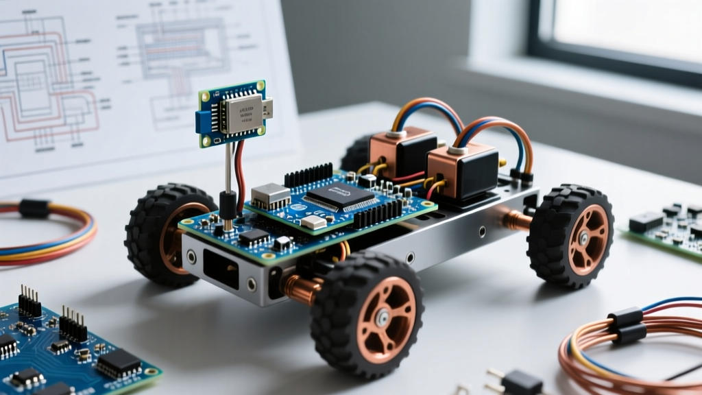

The Real-World Gap: Datasheets vs. Dirt and Grass
Most DIY robotics projects fail not because of bad code, but because of undersized or improperly wired motor control hardware. When you are building an outdoor autonomous rover, a desktop test on a smooth floor tells you nothing about the current spikes required to push a 15kg chassis through wet grass or over a door threshold. Selecting the right Arduino motor driver module requires looking past the marketing claims on cheap marketplace listings and understanding the physics of DC motors under load.
The Stall Current Trap: A motor rated for '12V, 1A continuous' does not draw 1A when it starts moving or when it hits an obstacle. At zero RPM (stall), the motor acts as a pure resistor. A typical 12V gearmotor with an internal resistance of 1.2 ohms will draw 10 Amps at stall. If your driver is rated for 2A continuous, it will instantly overheat or trigger its thermal shutdown.
According to the Pololu Motor Selection Guide, you must always size your motor driver based on the stall current of your motors, not the free-running current. In this guide, we will break down exactly how to choose, wire, and troubleshoot motor drivers for real-world, high-torque applications in 2026.
2026 Module Comparison Matrix: What to Actually Buy
The market is flooded with legacy and modern driver boards. Here is how the most common modules stack up for real-world rover applications, factoring in current market pricing and thermal realities.
| Module / IC | Topology | Cont. Current | Peak Current | Logic V | Motor V | Est. Price | Best Use Case |
|---|---|---|---|---|---|---|---|
| L298N | BJT (Bipolar) | 2A | 3A | 5V | 5-35V | $4 - $6 | Low-power indoor toys (Avoid for rovers) |
| TB6612FNG | MOSFET | 1.2A | 3.2A | 2.7-5.5V | 2.5-13.5V | $8 - $12 | Small 6V-9V micro-rovers, balancing bots |
| DRV8871 | MOSFET | 3.6A | 4.5A | 6.5-45V | 6.5-45V | $5 - $8 | Medium 12V rovers, single motor per IC |
| BTS7960 (43A) | MOSFET | 15A* | 43A | 5.5-27V | 5.5-27V | $12 - $18 | Heavy-duty 12V-24V outdoor rovers, actuators |
*Note on BTS7960: While the Infineon IC is rated for 43A, the cheap red PCB modules commonly sold online have thin copper traces that will melt or cause severe voltage drops above 15A continuous. Always reinforce the power traces with solder or use a heavy-duty breakout board.
Step-by-Step: Sizing for a 12V 4WD Rover
1. Calculating True Peak Current
Let us assume you are building a 4WD rover using four 12V planetary gearmotors. Each motor has a free-run current of 400mA and a stall current of 4.5A.
- Worst-Case Scenario: The rover gets high-centered on a rock. All four motors stall simultaneously.
- Total Stall Current: 4 motors × 4.5A = 18 Amps.
- Transient Spikes: Adding a 20% margin for inductive kickback and startup transients brings the requirement to ~21.6 Amps.
For this build, a dual-channel BTS7960 Arduino motor driver module (capable of handling ~15A per channel continuously) is the minimum viable hardware. You would wire the left two motors in parallel to Channel A, and the right two motors in parallel to Channel B.
2. Battery Chemistry and Voltage Sag
Motor drivers do not create power; they pass it. When an 18A load is applied to a standard 3S LiPo battery (12.6V fully charged), the internal resistance of the battery causes voltage sag. If your battery sags below the Undervoltage Lockout (UVLO) threshold of your motor driver (typically around 5.5V to 6.5V for high-power ICs), the driver will shut off, dropping the rover. For heavy-draw applications, consider using LiFePO4 cells, which maintain a flatter discharge curve under high C-rates, or parallel multiple battery packs to reduce internal resistance.
Critical Wiring Practices for High-Current Modules
Even the best motor driver hardware will fail if the wiring topology is flawed. Real-world environments introduce vibration, electromagnetic interference (EMI), and thermal cycling.
Star Grounding and Trace Limits
Never daisy-chain high-current motor grounds. Use a star grounding topology where the battery negative, motor driver power ground, and Arduino logic ground all meet at a single, heavy-duty terminal block. Furthermore, for currents exceeding 10A, do not rely on the PCB traces of budget modules. Solder 12 AWG or 14 AWG silicone wire directly across the power terminal pads and reinforce the PCB traces with a thick bead of rosin-core solder to increase the cross-sectional area and prevent thermal delamination.
EMI Suppression and Flyback Protection
Brushed DC motors are essentially spark generators. The carbon brushes create massive high-frequency noise that can couple into your Arduino's logic lines, causing erratic sensor readings or random I2C bus lockups.
- Motor Terminals: Solder a 100nF (0.1µF) ceramic capacitor directly across the metal terminals of every single motor. This shorts high-frequency noise before it travels down the wires.
- Bulk Decoupling: Place a large electrolytic capacitor (e.g., 2200µF to 4700µF, rated for at least 25V) across the main power input terminals of the motor driver module. This acts as a local energy reservoir to handle microsecond current spikes without pulling down the main battery voltage.
Advanced Troubleshooting: Beyond the Basics
The 'Arduino Reset' Brownout Loop
Symptom: The rover moves forward fine, but when you command a sharp turn or reverse direction, the Arduino resets and the rover stops.
The Physics: Reversing a motor requires the driver to short the motor's back-EMF and drive current in the opposite direction. This causes a massive, instantaneous current draw that collapses the shared power rail. If your Arduino is powered via a cheap buck converter tied to the same battery, the voltage drop triggers the Arduino's brownout detection (usually around 4.3V for the ATmega328P), causing a reset.
The Fix: Isolate the logic power. Use a dedicated, high-quality switching regulator (like an LM2596 or a modern synchronous buck module) with its own input capacitance, or power the Arduino from a separate 2S LiPo battery, ensuring the grounds are tied together.
Eliminating PWM Whine via Register Manipulation
By default, Arduino pins 3, 9, 10, and 11 output PWM at roughly 490Hz. When applied to a motor, this frequency falls squarely in the human hearing range, resulting in an annoying, high-pitched whine. Furthermore, low-frequency PWM can cause mechanical resonance in the gearbox.
To fix this, you can manipulate the Arduino's hardware timers to push the PWM frequency to 16kHz or 20kHz (ultrasonic). For example, on an Arduino Uno (ATmega328P), you can set Timer1 (Pins 9 and 10) to Fast PWM mode with no prescaling:
// Set Timer1 to 16kHz PWM (Mode 14, Prescaler 1)
TCCR1A = _BV(COM1A1) | _BV(COM1B1) | _BV(WGM11);
TCCR1B = _BV(WGM13) | _BV(WGM12) | _BV(CS10);
ICR1 = 999; // Top value for 16kHz at 16MHz clock
Warning: Changing timer registers will break default functions like delay() and the Servo library, which rely on Timer1. Plan your pin assignments accordingly.
The Optocoupler Clone Scam
Many heavy-duty BTS7960 modules advertise 'optocoupler isolation' to protect your microcontroller from high-voltage spikes. However, teardowns of sub-$10 modules from overseas marketplaces frequently reveal that the optocoupler ICs (like the PC817) are either missing entirely, replaced with dummy resistors, or wired incorrectly, offering zero galvanic isolation. If you are building a rover with expensive sensors and a premium flight controller, verify the isolation with a multimeter continuity test before deploying it in the field, or buy from reputable robotics vendors.
Expert Takeaways
Choosing an Arduino motor driver module for real-world applications is an exercise in thermal and electrical margin. Ditch the legacy L298N for modern MOSFET-based drivers like the TB6612FNG or BTS7960. Always size for stall current, suppress EMI at the motor source, and treat your power wiring with the same respect you would give to a mains electrical installation. For deeper insights into motor driver topologies and protection circuits, the Texas Instruments Motor Driver Fundamentals documentation remains an invaluable reference for advanced DIY engineers.