
The Truth About 'Laser Sensors' in the Arduino Ecosystem
When beginners search for a laser sensor Arduino project, they are usually met with two entirely different classes of hardware: simple laser dot emitters and advanced Time-of-Flight (ToF) distance sensors. Understanding the distinction is critical before you wire a single pin. As of 2026, the market is flooded with cheap modules, but choosing the wrong one will lead to frustratingly inaccurate data or fried logic pins.
Emitter vs. Time-of-Flight (ToF)
Modules like the KY-008 are not sensors at all; they are 5mW laser diode emitters. To use them as a 'sensor,' you must pair them with a photoresistor (LDR) to create a basic tripwire. While fun for burglar alarms, they cannot measure distance.
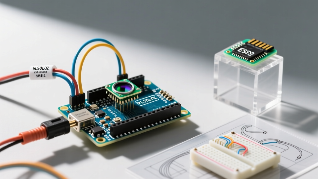
True laser distance measurement requires a Time-of-Flight (ToF) sensor. These modules emit an invisible, eye-safe Class 1 VCSEL (Vertical-Cavity Surface-Emitting Laser) pulse and measure the exact picoseconds it takes for the photons to bounce back. The undisputed champion for beginner Arduino projects is the VL53L0X (and its newer sibling, the VL53L1X), developed by STMicroelectronics.
Hardware Selection Matrix (2026 Market)
Before diving into the wiring, let us compare the three most common laser modules you will encounter on Amazon, AliExpress, and Adafruit.
| Module | Technology | Range | Interface | Avg. Price (2026) | Best Use Case |
|---|---|---|---|---|---|
| KY-008 | Visible Diode Emitter | N/A (Tripwire only) | Digital GPIO | $1.50 - $2.00 | Laser tripwires, visual alignment |
| VL53L0X | Infrared ToF (VCSEL) | 30mm - 2000mm | I2C | $4.00 - $9.95 | Object avoidance, liquid level sensing |
| TF-Luna | LiDAR (850nm VCSEL) | 200mm - 8000mm | UART / I2C | $16.00 - $22.00 | Drone altitude, long-range robotics |
For this tutorial, we will focus entirely on the VL53L0X, as it offers the perfect balance of precision, I2C simplicity, and budget-friendly pricing for microcontroller integration.
Deep Dive: VL53L0X Pinout and Voltage Warnings
The VL53L0X operates strictly on 3.3V logic. This is the most common failure point for beginners using 5V Arduino boards like the Uno or Mega. If you send 5V directly into the SDA or SCL lines without a breakout board that features onboard logic level shifting, you risk degrading the sensor's I2C transceiver over time.
Expert Warning: Never connect a raw 5V logic signal to the XSHUT (shutdown) pin on a bare VL53L0X chip. If you are buying a cheap generic breakout board without a voltage regulator and logic level MOSFETs, you must use a bidirectional logic level converter (like the BSS138 based modules, costing about $1.50) between the Arduino and the sensor.
Standard Breakout Pinout
- VIN / VCC: 3.3V to 5V (Only if the board has an onboard LDO regulator)
- GND: Common ground
- SCL: I2C Clock line
- SDA: I2C Data line
- XSHUT: Active low shutdown pin (Used for hardware reset or changing I2C addresses when using multiple sensors)
- GPIO1: Interrupt output (Optional, used to trigger an event when an object crosses a specific threshold)
Step-by-Step Wiring Guide (Arduino Uno R3 / R4)
Assuming you are using an Adafruit or high-quality generic breakout board with onboard 3.3V regulation and logic level shifting, follow this exact wiring sequence:
- Connect the sensor GND pin to the Arduino GND rail.
- Connect the sensor VIN pin to the Arduino 5V pin (the onboard regulator will step this down to 3.3V safely).
- Connect the sensor SDA pin to Arduino A4 (or the dedicated SDA pin near the AREF pin on newer clones).
- Connect the sensor SCL pin to Arduino A5 (or the dedicated SCL pin).
- Leave XSHUT and GPIO1 disconnected for basic single-sensor operation.
Note: If your wires exceed 15cm in length, the parasitic capacitance of the wires will degrade the I2C signal. You will need to solder 4.7kΩ pull-up resistors between the SDA/SCL lines and the 3.3V rail. For more on I2C bus physics, consult the Arduino Wire (I2C) Library Documentation.
Arduino Code: Reading Millimeters in Real-Time
To interface with the sensor, we will use the industry-standard Adafruit library. Open your Arduino IDE, navigate to Sketch > Include Library > Manage Libraries, and install Adafruit_VL53L0X.
The following code initializes the sensor, sets a standard timing budget, and outputs the distance in millimeters to the Serial Monitor.
#include 'Wire.h'
#include 'Adafruit_VL53L0X.h'

Adafruit_VL53L0X lox = Adafruit_VL53L0X();

void setup() {
  Serial.begin(115200);

  // Wait for serial port to open on native USB boards
  while (!Serial) { delay(10); }

  Serial.println('Adafruit VL53L0X test');

  // Initialize the sensor
  if (!lox.begin()) {
    Serial.println(F('Failed to boot VL53L0X. Check wiring!'));
    while(1); // Halt execution if sensor is missing
  }

  // Optional: Set measurement timing budget (higher = more accurate but slower)
  // lox.setMeasurementTimingBudgetMicroSeconds(50000);
}

void loop() {
  VL53L0X_RangingMeasurementData_t measure;

  lox.rangingTest(&measure, false);

  // Check if the reading is valid (RangeStatus 0 means OK)
  if (measure.RangeStatus != 4) {
    Serial.print('Distance (mm): ');
    Serial.println(measure.RangeMilliMeter);
  } else {
    Serial.println('Out of range / Signal lost');
  }

  delay(100); // 10Hz refresh rate
}
Real-World Edge Cases and Troubleshooting
Theory is clean; reality is messy. Here are the specific failure modes you will encounter when deploying a laser sensor Arduino setup in the field, and how to fix them.
1. The 'Out of Range' Sunlight Problem
The VL53L0X uses a 940nm infrared VCSEL. The sun also emits massive amounts of 940nm IR radiation. If your sensor is pointed toward a window or outdoors, ambient IR noise will blind the receiver, resulting in a RangeStatus 4 (Out of Range) error, even if an object is 10cm away.
The Fix: You cannot filter this via code. You must physically shade the sensor using a 3D-printed hood or shroud, or upgrade to the VL53L1X, which features superior ambient light rejection algorithms and a physical IR bandpass filter on the module.
2. I2C Address Conflicts on Multi-Sensor Rigs
Every VL53L0X ships with the hardcoded I2C address 0x29. If you are building a robot that requires three sensors (front, left, right), you cannot simply wire them all to the same I2C bus. They will collide and freeze the Arduino.
The Fix: You must use the XSHUT pin. Wire the XSHUT pin of each sensor to a separate digital GPIO on the Arduino. By pulling XSHUT LOW on two sensors, you put them to sleep. You then initialize the awake sensor, use the library's setAddress() function to change its I2C address to 0x30, and repeat the process for the others. The Adafruit VL53L0X Breakout Guide provides an excellent multi-sensor wiring diagram for this exact scenario.
3. Reflective Surface Blindness
Highly reflective surfaces (like mirrors or polished aluminum) or extremely light-absorbent surfaces (like black velvet) will skew readings. Mirrors cause the laser to bounce to a secondary surface and back, reporting a distance twice as far as reality. Black foam absorbs the 940nm photons, causing the sensor to report 'no signal'.
The Fix: Implement a software median filter in your Arduino code. Take 5 rapid readings, discard the highest and lowest values, and average the remaining three. This eliminates the 'ghost' readings caused by specular reflections.
Practical Project Idea: Touchless Liquid Dispenser
Now that you have reliable millimeter data, what can you build? A highly practical 2026 home-automation project is a touchless soap or water dispenser. By mounting the VL53L0X facing downward over a sink, you can set a threshold in your code (e.g., if (measure.RangeMilliMeter < 150 && measure.RangeMilliMeter > 50)). When a hand breaks this invisible laser plane, the Arduino triggers a 5V relay module to activate a 12V peristaltic pump for exactly 1.5 seconds. Because the ToF sensor ignores the reflective water surface and focuses on the physical hand, it is vastly superior to cheap PIR or basic IR proximity sensors that trigger falsely when the sun hits the sink.
References & Further Reading
- STMicroelectronics VL53L0X Datasheet - Essential for understanding the internal timing budgets and photon avalanche diode physics.
- Adafruit VL53L0X Breakout Guide - Detailed schematics on logic level shifting and multi-sensor XSHUT wiring.
- Arduino Wire (I2C) Library Documentation - Official reference for I2C bus constraints and pull-up resistor requirements.