
The State of Ultrasonic Sensing in Modern Microcontroller Ecosystems
Integrating an ultrasonic distance sensor Arduino setup remains one of the most foundational skills in embedded systems prototyping. However, the landscape has shifted dramatically. While the legacy HC-SR04 module is still widely available for roughly $1.50 to $3.00, the dominance of 3.3V logic microcontrollers like the ESP32-S3 and Raspberry Pi RP2350 in 2026 has exposed the limitations of 5V-only analog echo pins. Modern robotics and fluid-level monitoring now frequently demand waterproof transducers, I2C communication, and non-blocking driver architectures.
This guide bypasses basic tutorials and dives deep into the library ecosystem, driver-level timing bottlenecks, and advanced edge-case mitigation for ultrasonic peripherals.
Top Arduino Libraries for Ultrasonic Distance Sensors
Selecting the correct driver library dictates whether your microcontroller can handle concurrent tasks or if it will stall waiting for an acoustic echo. Below are the primary libraries used in professional and advanced hobbyist environments.
1. NewPing: The Non-Blocking Standard
Originally developed by Tim Eckel, NewPing remains the gold standard for ATmega-based boards. Its primary advantage over native code is the elimination of the blocking delay() and pulseIn() functions.
- Timer Interrupts: NewPing utilizes hardware timers (Timer2 on ATmega328P) to poll the echo pin asynchronously. This allows your main loop to execute thousands of instructions while waiting for a ping return.
- Timeout Enforcement: By defining a
MAX_DISTANCE(e.g., 200cm), the library calculates the exact microsecond timeout required (~12ms). If no echo returns, the function fails gracefully instead of hanging the MCU for a full second. - Multi-Sensor Arrays: Includes built-in event-driven ping scheduling for up to 15 sensors, inherently managing the 29ms acoustic settling delay required to prevent crosstalk.
2. Grove Ultrasonic Ranger Library
For rapid deployment using standardized connectors, Seeed Studio’s Grove library abstracts the pin toggling. While excellent for quick prototyping, it relies on blocking pulseIn() calls. It is best reserved for single-sensor applications where real-time loop latency is not a critical constraint.
3. Custom I2C/UART Drivers for Advanced Modules
As makers migrate to sensors like the RCWL-1601 (I2C/UART capable) or the A02YYUW (UART only), standard trigger-echo libraries become obsolete. In 2026, the best practice for these modules is utilizing hardware serial buffers or the Wire.h I2C library, parsing byte streams directly rather than measuring pulse widths.
Hardware vs. Library Compatibility Matrix
Not all ultrasonic transducers operate on the same protocol. Refer to this matrix to match your hardware with the correct driver approach.
| Sensor Model | Logic Level | Interface | Deadzone | Approx. Cost (2026) | Recommended Library |
|---|---|---|---|---|---|
| HC-SR04 | 5V | Trigger/Echo | 2 cm | $1.50 - $3.00 | NewPing |
| JSN-SR04T | 5V | Trigger/Echo | 20 cm | $4.50 - $6.00 | NewPing (Adjust Max Distance) |
| RCWL-1601 | 3.3V / 5V | I2C / UART / Echo | 2 cm | $3.00 - $4.50 | Wire.h (Custom I2C) |
| A02YYUW | 3.3V / 5V | UART (9600 baud) | 28 cm | $11.00 - $14.00 | HardwareSerial / SoftwareSerial |
Driver-Level Timing and the pulseIn() Bottleneck
To understand why library choice matters, we must examine the underlying hardware mechanics. When the trigger pin receives a 10µs HIGH pulse, the sensor emits eight 40kHz acoustic bursts. The echo pin then goes HIGH until the sound wave returns.
The native Arduino pulseIn() function measures this HIGH state. However, according to Texas Instruments' ultrasonic sensing fundamentals, acoustic wave propagation in air is relatively slow (approx. 343 meters per second at 20°C).
The Math of the Bottleneck: To measure a target at 400cm, the sound must travel 800cm round-trip. At 343 m/s, this takes roughly 23.3 milliseconds. If the sensor is pointed at an open void and no echo returns, a standard
pulseIn(pin, HIGH, 1000000)call will freeze your microcontroller for an entire second. In a 50Hz robotic control loop, a single missed ping destroys your PID control stability.
NewPing solves this by calculating the maximum possible round-trip time based on your defined MAX_DISTANCE and using hardware interrupts to abort the measurement the microsecond the timeout expires.
Advanced Edge Cases: Crosstalk, Multipath, and Thermal Drift
Deploying an ultrasonic distance sensor Arduino project in a controlled lab environment is trivial. Deploying it in a warehouse, a water tank, or a multi-robot swarm introduces severe physics-based edge cases.
1. Acoustic Crosstalk in Sensor Arrays
If you mount three HC-SR04 sensors on a rover chassis and fire them simultaneously, Sensor A will receive the echo from Sensor B’s transmission, resulting in phantom obstacles.
The Fix: Never fire sensors concurrently. Implement a sequential firing pattern with a minimum 29ms gap. For highly dynamic environments, add a randomized jitter to the delay to prevent harmonic resonance interference: delay(29 + random(15));.
2. Thermal Drift and Calibration
The speed of sound is not a constant; it is heavily dependent on ambient temperature. The formula for the speed of sound in dry air is v = 331.3 + (0.606 × T), where T is temperature in Celsius.
- At 0°C, sound travels at 331.3 m/s.
- At 40°C, sound travels at 355.5 m/s.
This represents a 7.3% measurement error across a 40-degree temperature swing. If your Arduino project operates outdoors or in an unclimate-controlled greenhouse, you must integrate a DS18B20 or BME280 temperature sensor. Pass the ambient temperature into your library's distance calculation to dynamically adjust the microseconds-to-centimeter divisor from the standard 58 to a temperature-compensated variable.
3. Multipath Interference and Beam Angle
Standard 40kHz transducers have a conical beam angle of roughly 30 degrees. If you mount a sensor too close to a flat floor or angled wall, the acoustic wave will bounce off the floor, hit the wall, and return to the sensor via a secondary path (multipath). This yields a distance reading that is longer than the direct line-of-sight. Mount sensors at least 15cm above ground level and utilize 3D-printed acoustic baffles (lined with open-cell foam) to narrow the effective beam angle to 15 degrees.
3.3V Logic Level Translation for Modern Microcontrollers
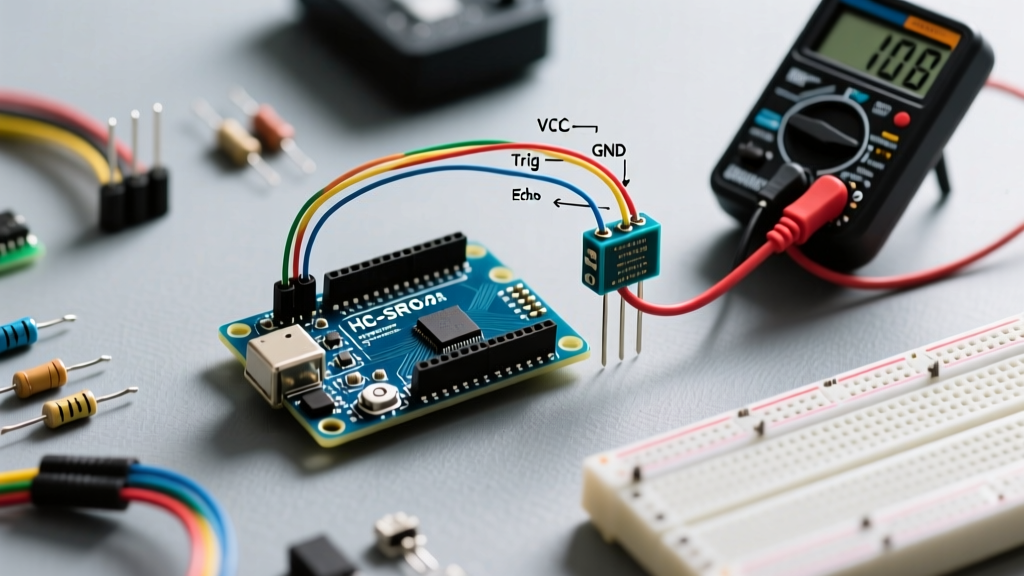
A critical failure point for modern makers is connecting the 5V Echo pin of an HC-SR04 directly to the GPIO of an ESP32, RP2040, or nRF52840. These microcontrollers are strictly 3.3V tolerant. Feeding a 5V pulse into an ESP32-S3 GPIO will permanently degrade the silicon over time, leading to erratic pin states and eventual thermal failure.
The Voltage Divider Solution:
You must step down the Echo pin voltage using a simple resistor divider. Connect a 1kΩ resistor (R1) in series with the Echo pin, and a 2kΩ resistor (R2) from the junction to GND. This yields a safe 3.33V logic HIGH. Ensure your resistors are 1% tolerance metal film to prevent voltage drift that could cause the MCU to misread the logic threshold.
Alternatively, bypass the analog echo entirely by adopting the RCWL-1601, which natively supports 3.3V I2C communication, eliminating the need for discrete passives and freeing up valuable GPIO pins on compact custom PCBs.
Summary
Successfully deploying an ultrasonic distance sensor Arduino system in 2026 requires moving beyond basic delay() loops. By leveraging non-blocking libraries like NewPing, compensating for thermal drift, managing acoustic crosstalk, and respecting 3.3V logic thresholds, you can build robust, industrial-grade distance measurement systems that survive real-world deployment.