
The Reality of Arduino pH Sensor Integration
Integrating an Arduino pH sensor into a hydroponics, aquaculture, or water quality monitoring project is notoriously frustrating for beginners. Unlike simple digital sensors, pH probes measure the millivolt potential difference across a glass membrane. This high-impedance analog signal is incredibly susceptible to electromagnetic interference, ground loops, and temperature fluctuations. According to the USGS Water Science School, accurate pH measurement requires strict temperature compensation, as the Nernst equation dictates that the electrode's millivolt output shifts by approximately 0.1984 mV per pH unit per degree Celsius.
In this comprehensive wiring and code guide, we will bypass the generic, low-resolution modules and focus on the industry-standard hobbyist setup: the DFRobot Gravity: Analog pH Sensor / Meter Kit V2 (SKU: SEN0161). Priced around $59.90 in 2026, it includes the E-201C-PT BNC probe, a signal conditioning board, and a DS18B20 waterproof temperature probe for real-time compensation.
Hardware Selection Matrix: Hobbyist vs. Industrial
Before wiring, it is crucial to understand where your chosen hardware sits on the reliability spectrum. Below is a comparison of the most common Arduino-compatible pH circuits available on the market.
| Module / Brand | Model / SKU | Avg. Price (2026) | Output Type | Temp. Compensation | Best Use Case |
|---|---|---|---|---|---|
| Generic Unbranded | LM393 Comparator Board | $12.00 | Digital (High/Low) | None | Simple threshold alarms (e.g., 'is water acidic?') |
| DFRobot Gravity V2 | SEN0161 (E-201C-PT) | $59.90 | Analog (0-5V) | Manual (via DS18B20) | DIY Hydroponics, Aquariums, School Labs |
| Atlas Scientific | EZO pH Circuit | $149.99 | I2C / UART Digital | Automatic (Internal) | Commercial Aquaculture, Lab Automation |
Wiring the DFRobot V2 & The Ground Loop Trap
The most common point of failure when wiring an Arduino pH sensor is introducing 50Hz/60Hz AC noise from a laptop's USB power supply. Because the pH probe acts as an antenna for electromagnetic noise, powering your Arduino via a standard laptop USB connection will cause the analog readings to fluctuate wildly (often swinging ±0.5 pH units).
⚠️ Critical Wiring Warning: Ground Loops
Never power your Arduino and peripheral pumps (like peristaltic dosing pumps) from the same power rail without opto-isolation. The back-EMF from pump motors will travel through the ground plane, corrupting the high-impedance pH signal. Always use an isolated DC-DC converter or a dedicated 5V power supply for the sensor board.
Pinout & Connections
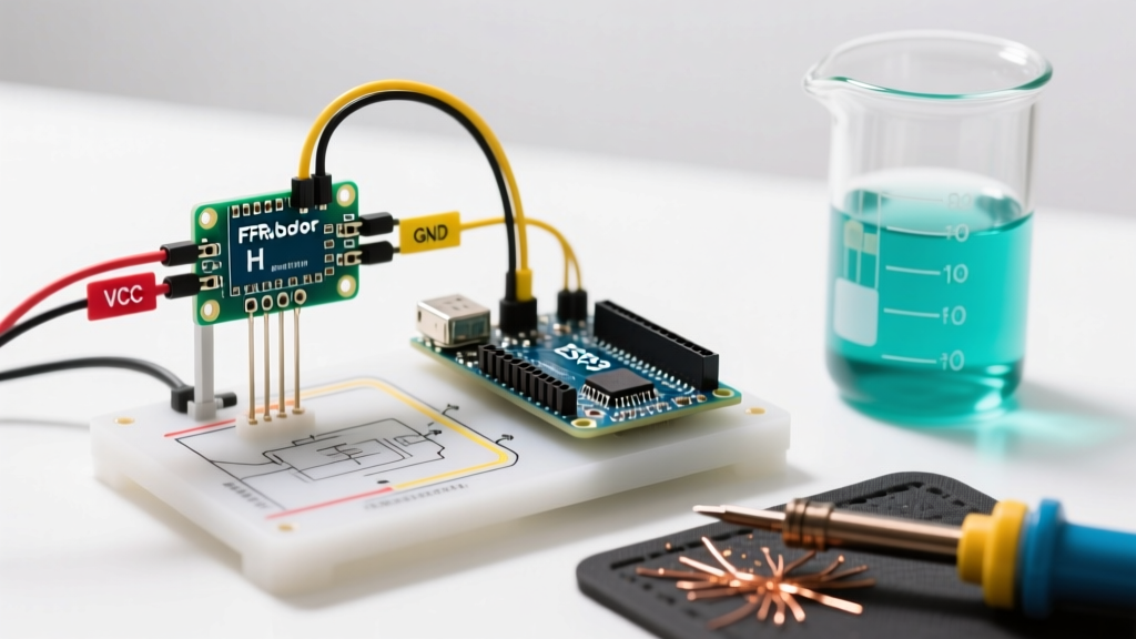
- pH Signal Board VCC: Connect to Arduino 5V. (Do not use 3.3V; the
analogReference(DEFAULT)on an Uno requires 5V for full 10-bit ADC resolution). - pH Signal Board GND: Connect to Arduino GND.
- pH Signal Board OUT: Connect to Arduino Analog Pin A0.
- DS18B20 VCC (Red): Connect to 5V.
- DS18B20 GND (Black): Connect to GND.
- DS18B20 Data (Yellow/White): Connect to Digital Pin 2. Must include a 4.7kΩ pull-up resistor between Data and 5V.
The 3-Point Calibration Protocol
According to EPA water research guidelines, accurate environmental pH monitoring requires multi-point calibration to establish the precise slope and offset of your specific electrode. The glass membrane degrades over time, meaning factory defaults are never accurate for long-term deployment.
Required Materials
- pH 7.00 Buffer Solution (Zero-point calibration)
- pH 4.01 Buffer Solution (Acidic slope calibration)
- pH 10.01 Buffer Solution (Alkaline slope calibration - optional but recommended for hydroponics)
- Distilled water for rinsing (Never wipe the glass bulb with a towel; it creates static charge and damages the gel layer).
Production-Ready Arduino C++ Code
The following code utilizes the OneWire and DallasTemperature libraries to read the DS18B20, applies a moving average filter to the analog pH readings to smooth out ADC noise, and calculates the temperature-compensated pH value. You can verify standard analog reading behaviors via the official Arduino analogRead() documentation.
#include <OneWire.h>
#include <DallasTemperature.h>

#define ONE_WIRE_BUS 2
#define PH_PIN A0

OneWire oneWire(ONE_WIRE_BUS);
DallasTemperature sensors(&oneWire);

// Calibration Constants (Derived from your specific 2-point calibration)
// Adjust these based on your serial monitor output during calibration
const float VOLTAGE_7 = 2.52; // Expected voltage at pH 7.0
const float VOLTAGE_4 = 3.04; // Expected voltage at pH 4.0

const float SLOPE = (7.0 - 4.0) / (VOLTAGE_7 - VOLTAGE_4);
const float OFFSET = 7.0 - (SLOPE * VOLTAGE_7);

float phReadings[10];
int readIndex = 0;

void setup() {
  Serial.begin(115200);
  sensors.begin();
  analogReference(DEFAULT); // Ensure 5V reference on Uno/Mega

  // Initialize array
  for (int i = 0; i < 10; i++) {
    phReadings[i] = 0;
  }
  Serial.println("Arduino pH Sensor System Initialized...");
}

void loop() {
  // 1. Read Temperature
  sensors.requestTemperatures();
  float tempC = sensors.getTempCByIndex(0);

  // 2. Read Analog pH & Apply Moving Average
  int rawADC = analogRead(PH_PIN);
  float voltage = (rawADC * 5.0) / 1024.0;

  phReadings[readIndex] = voltage;
  readIndex = (readIndex + 1) % 10;

  float avgVoltage = 0;
  for (int i = 0; i < 10; i++) {
    avgVoltage += phReadings[i];
  }
  avgVoltage /= 10;

  // 3. Calculate pH with Temperature Compensation (Nernst Equation approx)
  // Standard Nernst slope is 59.16 mV/pH at 25°C. Adjusts by ~0.1984 mV/°C
  float tempCompFactor = 1.0 + ((tempC - 25.0) * 0.00335);
  float uncompensatedPH = (SLOPE * avgVoltage) + OFFSET;
  float finalPH = uncompensatedPH * tempCompFactor;

  // Constrain to realistic physical limits
  finalPH = constrain(finalPH, 0.0, 14.0);

  Serial.print("Temp: ");
  Serial.print(tempC);
  Serial.print("C | Voltage: ");
  Serial.print(avgVoltage, 3);
  Serial.print("V | pH: ");
  Serial.println(finalPH, 2);

  delay(1000); // 1 second read interval
}
Troubleshooting & Edge Cases
Even with perfect wiring and code, pH sensors exhibit unique failure modes. Here is how to diagnose the most common issues encountered in 2026 field deployments:
1. Readings Drift Continuously in One Direction
Cause: The reference electrode's internal KCl (Potassium Chloride) electrolyte is depleted, or the ceramic junction is clogged.
Fix: Soak the probe in 3M KCl storage solution for 24 hours. Never store a pH probe in distilled or reverse-osmosis water. Pure water will leach the ions out of the glass membrane via osmosis, permanently destroying the probe's response time.
2. Extreme Noise / Erratic Jumps (e.g., pH 4 to pH 10)
Cause: Ground loop interference or a damaged BNC connector shield.
Fix: Disconnect the laptop USB. Power the Arduino via the barrel jack using an isolated 9V DC adapter. Ensure the BNC connector is screwed in tightly and the outer metal shield is making solid contact with the signal board's ground plane.
3. Slow Response Time (Takes >2 minutes to stabilize)
Cause: The glass bulb is coated in oils, biofilm, or mineral scale.
Fix: Clean the probe. For organic oils, soak in a mild detergent solution. For mineral scale (common in hard water aquaculture), soak in a 0.1M HCl (Hydrochloric acid) solution for 15 minutes, then rinse thoroughly with distilled water and re-calibrate.
Frequently Asked Questions
Can I use a 3.3V microcontroller like the ESP32 with this sensor?
Yes, but you must power the DFRobot signal board with 5V, and use a voltage divider (e.g., 10kΩ and 20kΩ resistors) on the analog OUT pin to step the 0-5V signal down to the ESP32's 0-3.3V ADC range. Alternatively, use an ADS1115 16-bit external ADC for vastly superior resolution.
How often should I recalibrate the Arduino pH sensor?
For critical hydroponic dosing, calibrate weekly. For general aquarium monitoring, a monthly 2-point calibration (pH 4 and pH 7) is sufficient to account for electrode aging.